I am currently trying to simulate the “H-Bridge Sine Wave Inverter Circuit using Arduino” (based on the IR2112 driver) in QSPICE.
To give some context:
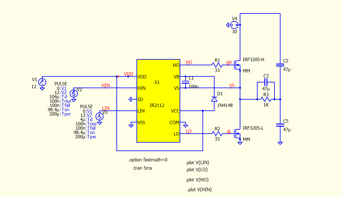
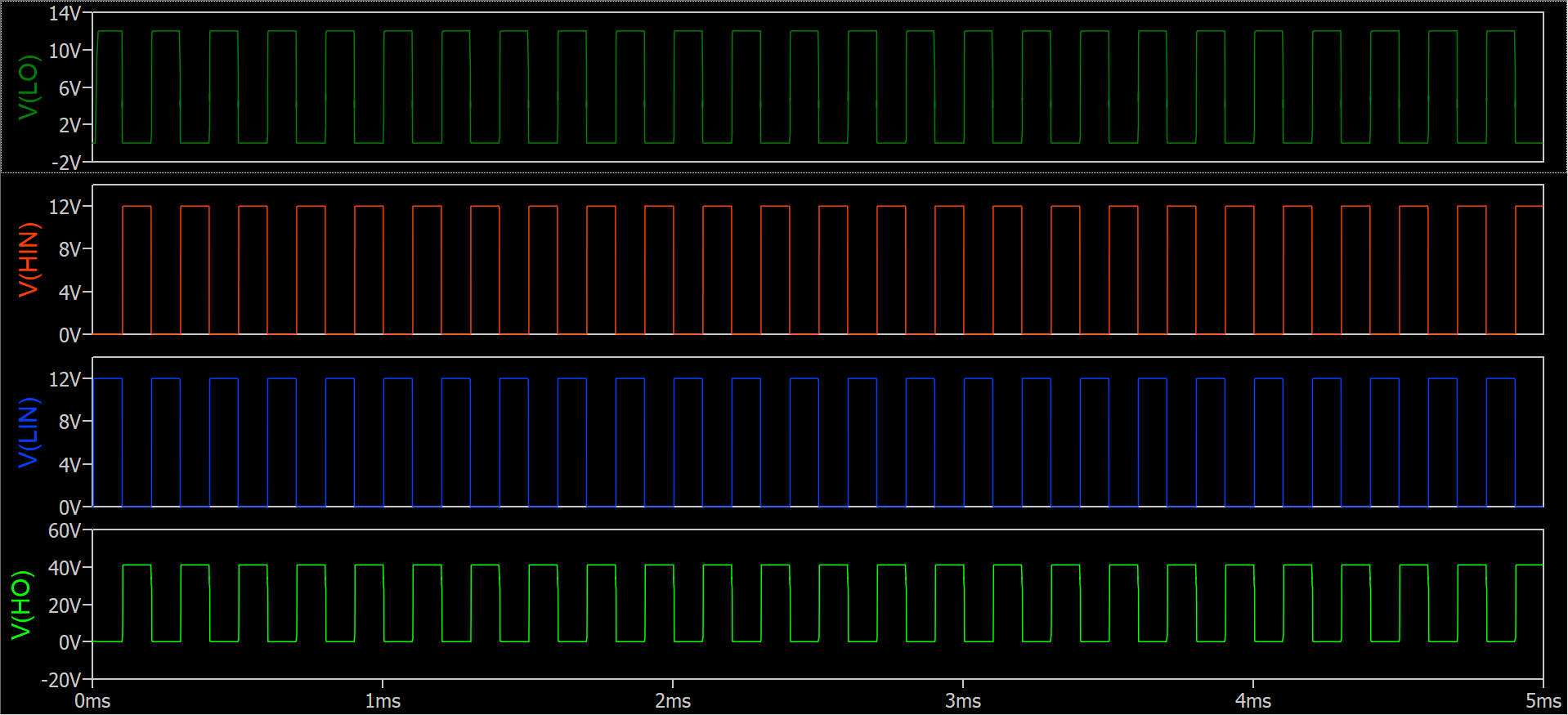
I have already successfully built/simulated a 30V DC-DC Half-Bridge. My goal now is to move from DC-DC to a DC-AC Full-Bridge topology using this specific circuit design.
However, I am struggling to get the simulation running correctly.
My question is:
Has anyone here successfully simulated this specific transition — from DC-DC to DC-AC using an IR2112 F-Bridge — in QSPICE before?
I have attached two images:
My working DC-DC setup (for reference).
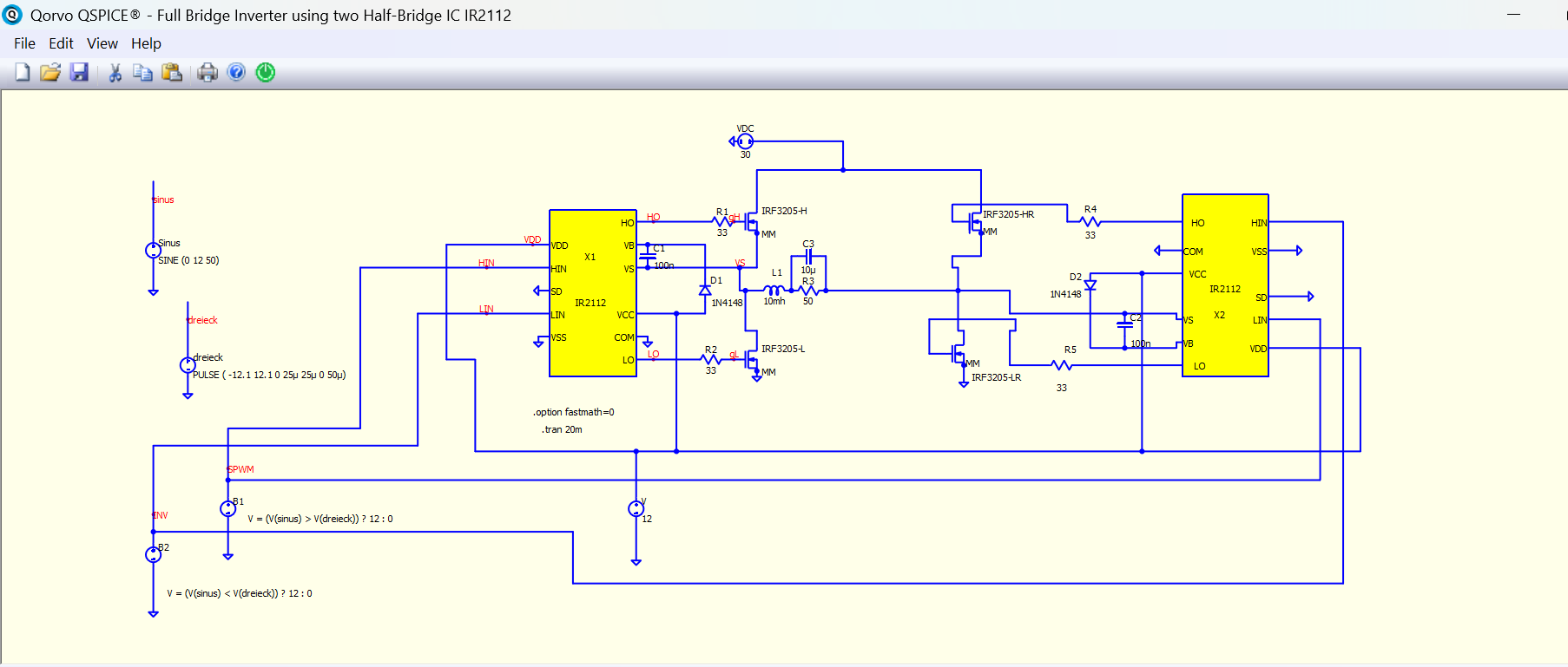
My attempt at the Full-Bridge DC-AC simulation (where I am currently stuck).
Any experience or advice on whether this specific Arduino/IR2112 inverter circuit runs well in QSPICE would be very helpful.
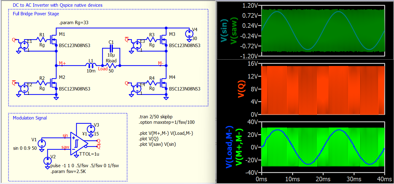
I don’t recommend using a B-source for the comparator. Instead, pick the comparator.
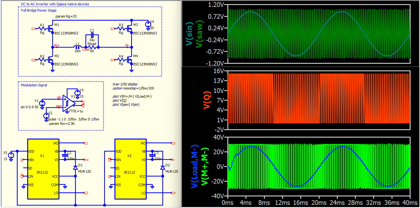
Including the IR2112 may only reduce your simulation speed. Depending on the level of simulation you are aiming for, I typically suggest building a simulation with native components before considering complex subcircuits. They may not offer many benefits, as it is primarily an isolation gate drive model. You should ensure that your circuit is running properly before adding those subcircuit models, as if anything goes wrong, you might face a complete loss.
DC-AC Inverter - Basic (Native).qsch (20.1 KB)
This is the circuit I initially created to ensure that the modulating signal and power stage appear satisfactory.
DC-AC Inverter - Basic (IR2112).qsch (47.1 KB)
This is the circuit with the IR2112. Using net labels for a clear schematic (prevent many wires) can aid in troubleshooting.
Thank you, KSKelvin, for your feedback. I looked into it again today and it now works for me with B-Source. I get the sinusoidal waveform at the load and the SPWM is working correctly.