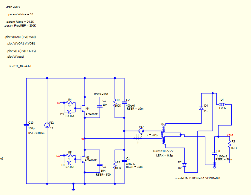
I am trying to simulate a half bridge in qspice. Looks like there is some issue with the leakage inductance of the transformer. Even with a very liitle leakage, the voltage across the secondary of the transformer looks weird. It works perfectly fine with 0 leakage inductance. And Vout is just 2.66V when it is set to be 5V. Can I get any help with this? Is it to do with the parameters set on the simulation?
Please send your schematic as well.
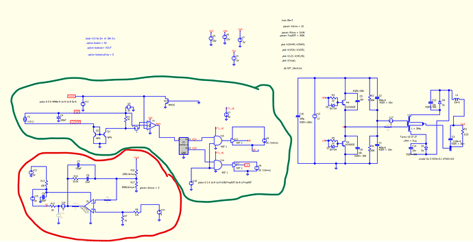
Marked in green is the controller part and in red is the feedback circuit.
Half bridge test ckt.qsch (58.9 KB)
Half bridge test ckt.cpp (1.5 KB)
Let’s simplify the circuit to focus solely on your question. Are you indicating that you don’t understand why the voltage of the secondary appears as in the second picture when the leakage inductance is set to 1uH, for instance?
Half Bridge with Main Transformer Leakage.qsch (24.8 KB)
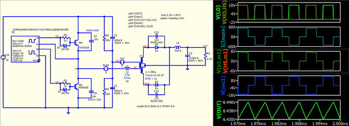
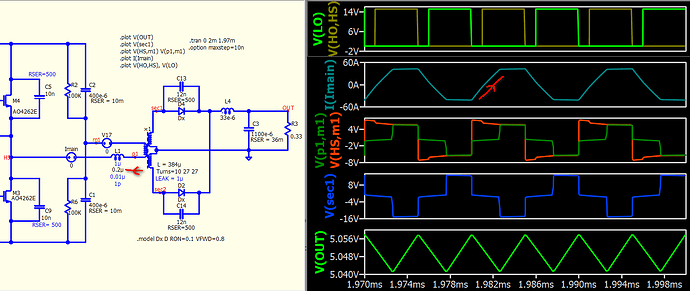
Leakage set to 1pH
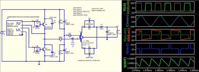
Leakage set to 1uH
Yes. I don’t understand why with a little increase in the leakage inductance as shown in the second picture the voltage of the secondary and the current through the primary windings of the transformer appear that way.
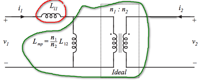
To understand this, you need to have a comprehensive understanding of how a transformer works. Here is a typical transformer model with a magnetizing inductance in parallel with an ideal transformer, along with leakage inductance in primary. The ×-device is quite unique; without L and Leak, it models the ideal transformer (i.e., the turn ratio and voltage/current relationship). However, this type of transformer does not physically exist because a transformer is constructed with a coupled inductors. Therefore, it must have inductance, which includes magnetizing inductance and leakage inductance. If you solely use the ×-device with L and LEAK, everything is combined, making it somewhat challenging to analyze.
In my example, I have used the ×-device with Lm (green) and L1 as leakage (red). In below simulation with a leakage of 0.2uH, which is significant enough to restrict di/dt (rate of change of primary current). As di/dt is limited, the current cannot instantly shift from negative to positive during switching actions. The voltage drop across the ideal transformer is nearly zero during this di/dt-limited period by leakage, hence you won’t observe significant coupling into the secondary during this time, which is coupled through that ideal transformer in the model.
You can try gradually increasing the leakage value and observe the effects from the schematic I provided in the previous post. This may help you grasp what is happening.
