@carlos.silva@Wassim_Qorvo I’m hoping you can help provide some clarity and guidance on getting started with the DWM3001C. After spending a couple of days researching and experimenting, I have a couple of questions.
Can the DWM3001C be used as a standalone device (with just a battery), or does it need a host controller? It incorporates the nRF52833, which has a Cortex-M4, so I would think that it can run on its own once it’s programmed? For example, if I took a DWM3001CDK, programmed it, then desoldered the DWM3001C module from the dev board and provided it with power, would it run the programmed code the same as if it was still soldered to the dev board?
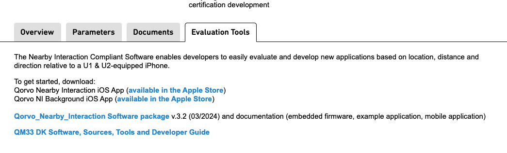
Assuming it can run standalone, is there an SDK/firmware available for it? I’ve found the DWM3001CDK DK Software, Sources, Tools and Developer Guide, but this has a lot of content specific to the DWM3001CDK that is not on the DWM3001C (e.g. controlling LEDs, input from the buttons, etc.).
Assuming it can run standalone, what is the recommended/standard way to program a large number (thousands) of DWM3001C modules?
For the DWM3001CDK, I have been able to build and download the DWM3001CDK DK Software, Sources, Tools and Developer Guide SDK package to the module using SES, but it is unclear how we should actually use this SDK/firmware for a real application. In our case we need to:
Scan for nearby UWB anchors
Range to each one of them
Read a high/low value from a GPIO pin
Transmit all of this data (range to each anchor, GPIO value) to a computer via BLE
Repeat on an interval
Once the SDK/firmware is built and downloaded to the module (per section 9 of the User Guide), where/how do we actually develop an application to utilize that SDK/firmware? Are there any examples available for this?
DWM3001C is actually a module produced by Qorvo that you can acquire. DK is just Dev Kit for that module, which includes the power connection, LEDs, buttons, and a built-in J-Link. https://www.qorvo.com/products/p/DWM3001C
All software listed for DWM3001CDK will work as is with the module, also examples for Nordic nRF528XX (maybe a pin reallocation will be needed in this case).
Good question, I see some options but with a lot of “ifs”. The best idea is to contact your sales representative and ask for support: Contact a Qorvo Sales Representative - Qorvo
You can start with the Developer Guide and understand how the UWB tasks are set, how UWB is configured, and where the results are reported. The example software implements a command line interface, you can configure and start UWB using that or even create a Python script to test what you want. When you’re happy with the sequence, then you can check how the application handles each command and bring it to your own app. About GPIO and BLE, you can check Nordic examples folder inside their SDK folder, keep in mind that you’re developing for an nRF52833 after all.
You can always come here with more specific questions, like “How to start the app as an initiator?”
Hope it helps and good luck!
Thanks for the very quick and thorough response. I managed to sort through the SDK and understand now how the pins would be reallocated if I mounted the DWM3001C on a custom board, instead of using it on the DWM3001CDK.
To confirm, the J-link debugger isn’t actually needed for the DWM3001C to run, correct? It’s only used for programming and debugging?
Based on your response, a couple more questions then, if I may:
Could you describe the difference between the CLI and UCI example projects in the DWM3001C SDK? It looks like they use exactly the same code, but the Project/Solution files themselves are different.
I may have a fundamental misunderstanding about how this is intended to function. It seems that the two SDK projects (CLI and UCI) are intended to run continuously and accept commands over serial (CLI) or UART/USB (UCI). This implies that there’s some external host that is sending those commands. But, what if I don’t have an external host, and I want the DWM3001C to be entirely self-contained with a pre-programmed loop of operations/commands to run (those described in question 4 above)? This might be what you mean by “bring it to your own app”, but it’s unclear how to create a new continuous task that runs these commands.
You mention using the Nordic examples, which makes sense, but how does one integrate the Nordic example code (BLE, GPIO) into the example DWM3001CDK projects (e.g. DWM3001CDK-DW3_QM33_SDK_UCI-FreeRTOS.emProject)? The main.c file for the Qorvo projects appears to start several tasks and a scheduler (which never returns); how would I start an ongoing task that, on an interval, uses the UWB module and transmits certain data from that over BLE?
This may not be related, but do you know how to have .h files appear in the SES file explorer? I’m not sure if it’s an SES thing or a configuration settin in the Qorvo SDK projects, but it’s only showing the .c files.
I am working on a standalone solution (just battery, no USB/UART) for ToF ranging. I am using the “DWM3001CDK DK Software, Sources, Tools and Developer Guide” with DWM30001CDK, but there are similar issues so I decided to reply to this thread.
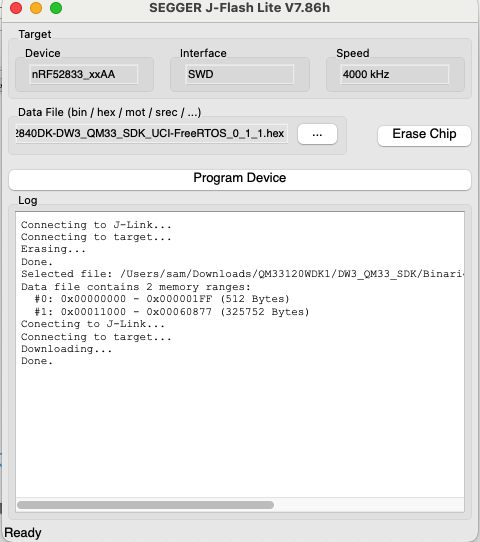
As far as I understand it the provided firmware DWM3001CDK-DW3_QM33_SDK_CLI-FreeRTOS_0_1_1.hex is built for the NRF52833, and Segger J-Flash Lite flashes it directly to the DWM30001C. However, the FW still relies on inputs from the UART to configure and start the applications (initf, respf). I am looking into the DWM3001CDK-DW3_QM33_SDK_CLI-FreeRTOS.emProject, and try to make it running in a standalone fashion, but I don’t yet understand how all the bits and pieces work together.
The CLI is the Command Line Interface that I mentioned in 4, UCI (UWB Command Interface) is a standard for software applications to communicate with UWB devices, the scripts folder has an example using UCI over uart.
I suggest you try the CLI first, connect a flashed DWM3001CDK to a PC using the User USB (J20), the PC will find a new COM Port, then you can use your preferred serial terminal to connect to it, then try the command “help”.
You got it right, but it doesn’t require to have an external host. After starting a board with a specific configuration you can use the CLI command “save” to write to flash your UWB configuration and function.
This is something you can try right now, open two terminals for two boards, set one as responder and the other as initiator they should start TWR, then save the initiator, keep the responder connected for monitoring and unplug the initiator, plug the initiator into a power supply or powerbank. It may take a few seconds but TWR between them will start again.
To set your application you need to change the default_config values or decide on how to set it (e.g.: via BLE), and then rewrite main() to start a specific role instead of loading the saved state from flash or waiting for a command, but then I recommend you to get familiar to the application first.
@christian.i, look for the “app_definition_t” type in /Src/Apps/Src/common/app/common/app.c, there you can set a variable (let’s say, “fira_initiator_app”) and configure it as the DEFAULT_APP. Also, take a look at how the “default_app” is loaded.
You can start following how it is implemented for other components, like USB CDC in the CLI example. The Nearby Interaction project uses the same structure and implements BLE: https://www.qorvo.com/products/d/da008212
I don’t know, I almost always use “right click->Go To Declaration” and few times I expand a .c file and look at its dependencies.
First of all, thank you for great explanation.
I could check distance between two DWM3001C through CLI emProject. (calibration & frequency matching needed)
CLI result : [{“Addr”:“0x0000”,“Status”:“Ok”,“D_cm”:61,“LPDoA_deg”:0.00,“LAoA_deg”:0.00,“LFoM”:0,“RAoA_deg”:0.00,“CFO_100ppm”:-639}]}
My goal is getting the distance&angle of tag from the anchor. (Both will be DWM3001C which include nrf52833)
However, I couldn’t find out how to use UCI over uart.
Can you explain how to use simply?
Is there any way to get LPDoA_deg data from single anchor (DWM3001C)? QM33120WDK1 is too expensive.
1/ In this same package for DWM3001CDK https://www.qorvo.com/products/d/da008604, you can find binary for UCI.
In SDK developer guide, in section 6.3 you can find example on how to use UCI over uart.
2/ Technically, this not possible to get LPDoA_deg with single antenna chip. That’s why you would need QM3120WDK1 for this.
Hi Carlos, What if I want to modify the firmware in order to have one board working immediately as responder once connected without any ‘respf’ command on terminal?
Until now I’ve just used CLI for TWR between one initiator & 1 responder.
Thank You in advance.
Then, go to main() and add scan_fira_params right after “DefaultTaskInit()”
scan_fira_params("", false); // Change to true if initiator
By doing this the app should be able to start FiRa TWR in the startup.
You may also need a High-Frequency Clock fix to start it with USB disconnected:
In main() look for BoardInit(), it calls peripherals_init() which has the clock initialization.
There you will find a call for nrf_drv_clock_lfclk_request(NULL), right before this line, you should add the nrf_drv_clock_hfclk_request(NULL).
This single call will solve the problem, but Nordic sets the call with verification before proceeding:
   nrf_drv_clock_hfclk_request(NULL);
   while (!nrf_drv_clock_hfclk_is_running())
   {
       // spin lock
   }
Hi Carlos Thank You for your help.
It is possibile that when i build the project i display an error? do i have to put the:#define DEFAULT_APP helpers_app_fira
also in fira_fn.c where:
extern const app_definition_t helpers_app_fira[];


/* Fira Node and Tag */
REG_FN(f_initiator_f)
{
    const char *ret = CMD_FN_RET_OK;

    scan_fira_params(text, true);
    show_fira_params();

    const app_definition_t *app_ptr = &helpers_app_fira[INITF_OFFSET];
    EventManagerRegisterApp(&app_ptr);

    return (ret);
}

REG_FN(f_responder_f)
{
    const char *ret = CMD_FN_RET_OK;

    scan_fira_params(text, false);
    show_fira_params();

    const app_definition_t *app_ptr = &helpers_app_fira[RESPF_OFFSET];
    EventManagerRegisterApp(&app_ptr);

    return (ret);
}

REG_FN(f_pdoa_average)
{
    const char *ret = CMD_FN_RET_OK;

    char *str = CMD_MALLOC(MAX_STR_SIZE);

    int n, dummy;

    if (str)
    {
        rf_tuning_t *rf_tuning = get_rf_tuning_config();
        n = sscanf(text, "%9s %d", str, &dummy); // to count the number of arguments

        if (n == 2)
        {
            rf_tuning->paverage = (int16_t)val; // val is the input
        }

        int hlen;

        hlen = sprintf(str, "JS%04X", 0x5A5A);
        sprintf(&str[strlen(str)], "{\"AVERAGE\":%d}", rf_tuning->paverage);

        sprintf(&str[2], "%04X", strlen(str) - hlen);
        str[hlen] = '{';
        sprintf(&str[strlen(str)], "\r\n");
        reporter_instance.print((char *)str, strlen(str));

        CMD_FREE(str);

        ret = CMD_FN_RET_OK;
    }


    return (ret);
}
Hi Carlos, one question, in this way I don’t need the responder to be connected to a pc anymore?
I mean with these changes it should be possibile that the responder starts automatically without any commands even if I connect it to a power bank, since I don’t have many computers or tablet, right? * Thanks againThank you.
thanks now it works, do you know also how to modify the code in order to have multiple responder(I have 4 more) and 1 single initiator. I guess I should do some modification about addresses but I don’t know ho to proceed.
THanks
and removed cable from j9 and moved to J20… d20 light blinks (like it did before on other firmware)
no USB port is created… (linux or mac) …
I have other USB based boards what DO create usb ports when plugged in on either dev system
what am I doing wrong?
I want to do fira ranging (one to many) , cli/uci I don’t care… but I can’t get the port, so can’t use either interface…
one question … the prior firmware, used in sync with the apple nearby support… is it compatible with either cli or uci?
I have 50 devices with the nearby firmware as responders…
if I reflash the nearby firmware, then the Qorvo nearby app can find it and my app sees it.
if I reflash the lastest sdk for cli , then neither the qorvo Nearby app nor my app can see it.
SO, its not active like the doc says
DW3 QM33 SDK Developer Guide (just requested and download from Qorvo)

6.2 Interfaces
The SDK currently supports different interfaces for UCI commands.
6.2.1 Physical transport
• UART: all targets (115200,8N1, no flow control) or USB (CDC ACM class) on boards with USB peripheral.
6.2.2 Active interface selection
**At boot time, all interfaces available on a board will be enabled in reception mode and are ready to handle a UCI command**. Once a command is received on a transport peripheral, it will become the active interface and will be dedicated to UCI transactions.
Please follow Board Connections on how to connect those interfaces to your board.
and just to clarify the QM33 sdk
it is listed as eval for the cdk board
Would you mind updating this solution? It doesn’t work as of now. scan_fira_params does not seem to exist anywhere in the code for me and it looks like it was replaced with another function.
This is a quite old post, and many changes have been made in the SDK since then.
Please take a look at the documentation for the SDK version you’re using, to enable the standalone use of the dev boards.
I’m going to close this topic, and if you have a more specific question, feel free to open a new topic. I’ll be glad to help you there.