Hi everyone,
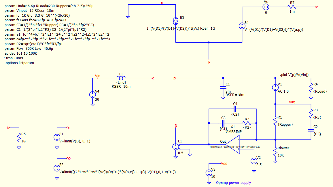
I’m working on a linear PWM switching model operating in voltage mode. The model uses behavioral current and voltage sources to represent the average behavior of a boost converter single pole double throw (SPDT) configuration.
I’ve encountered an issue with the behavioral current source (B3): the simulator reports that the negative terminal is a floating node. In my design, the negative terminal is connected to GND, and the positive terminal connects to GND through C1 and R4, so the circuit should be complete.
Here’s a snapshot of the configuration:
Has anyone experienced this before? Any ideas on what might be causing this issue or how to resolve it would be greatly appreciated.
Thank you!