Hello everyone,
I’ve read that the spice doesn’t have a minimum or fixed timestep. Quoting: . But can it be different for the simulation of C block file?
The problem with this approach is that you cannot really emulate a microcontroller, which depends on external/internal fixed clock.
Because of this by running a i++ to 255 as a counter, is the same as running it to 10 or whatever number.
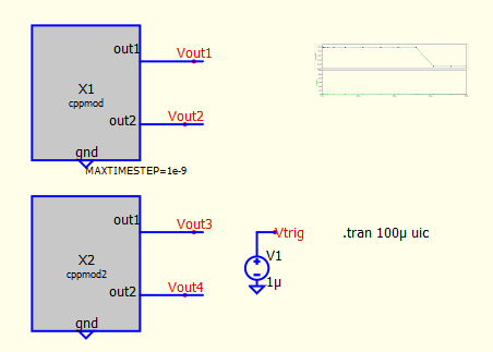
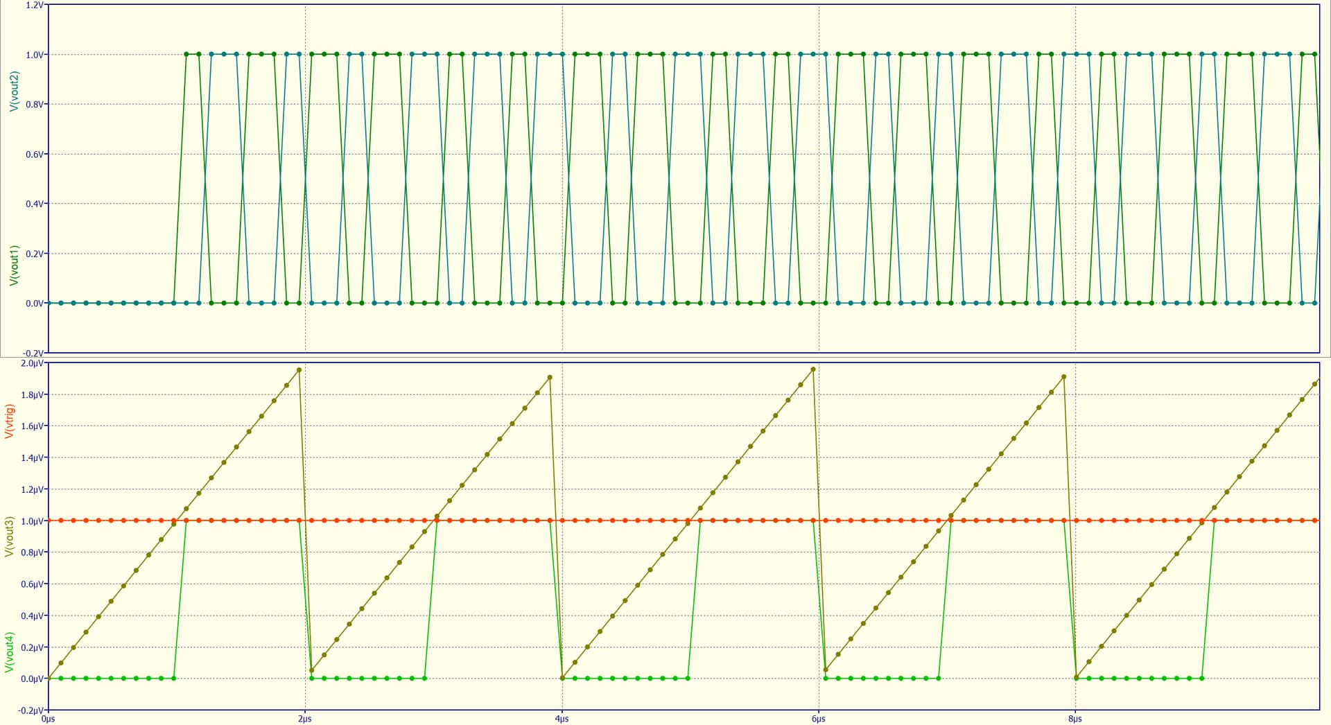
Also, when creating a computing a sawtooth waveform, you can see that the trigger point is not constant. Mostly because there are just several points on the interval.
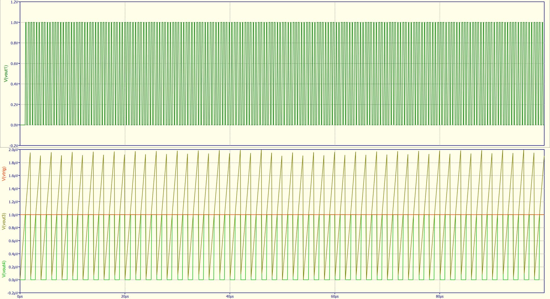
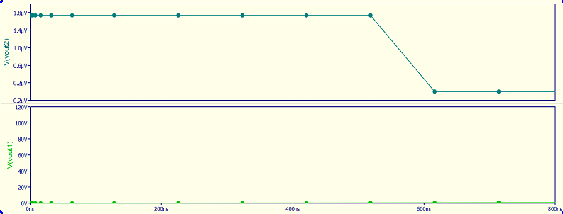
That of course happens because of the variable time step. Below example you can see how crowded the points are at the beginning vs the rest of the simulation:
My question, again is, can it be implemented in the future a way of adjusting setting minimum timestep/tick only on the C++/verilog block? (An example would be like in PSim for Simplified C block, at the simulation control).
Community, admins, thank you very much,
What I did there is set the time step in MaxExtStepTime() to force the first simulation point to happen “soon enough.” Then, as each sample is read from the file, I calculate/save the next time point. In Trunc(), I force the next time point to be at that saved time. But, frankly, I’m not sure this is how this is intended to work.
I considered using a pulse voltage source as an input clock (test for rising or falling edge in the main entry point). Perhaps that would work better for your needs.
I’ve tried with the pulse source to emulate the input clock by instructing the c++block to do every instruction. The results? Takes like, more than it should. And maybe it does follow every thick, but when you zoom it, it just skips some points.
Personally, I found it hard to read and understand your code, so I would not use it. For sure I have to learn more code.
It would be much easier if it were already a variable like t, that would tell the tick/delta t between each run.
I’ve read Michael’s reply in the previous post,
and I saw that by following that instruction it used more points, which somehow gave a good enough solution, for now…
I encountered the same problem years ago. The key element in constructing a microcontroller clock generator is an analog controlled digital delay. The classical circuit solution is a capacitor charged with a constant current and a comparator to detect when the cap. voltage crosses a threshold level. Works perfectly in hardware but produces clock jitter in a simulation because of roundoff errors and discrete timesteps. The solution is to build an analog-controlled digital delay in Verilog A or C++. I did it in VHDL-AMS. You can probably understand that code well enough to translate for Qspice…
entity d_dly_a_controlled is
generic (K : real := 176.6e-9; – scale factor in dly := KQctl + xtra_dly [sec/unit]
xtra_dly : real := 0.0); – additive term in dly := KQctl + xtra_dly [sec]
port (signal inp : IN std_logic; – digital input
signal outp : OUT std_logic; – digital output
quantity Qctl : IN real); – Analog control input [no units]
end entity d_dly_a_controlled;
architecture default of d_dly_a_controlled is
begin
process (inp) is
variable dly : real := KQctl + xtra_dly; – delay
begin
dly := KQctl + xtra_dly;
outp <= transport inp after dly * 1 sec; – delayed input
end process;