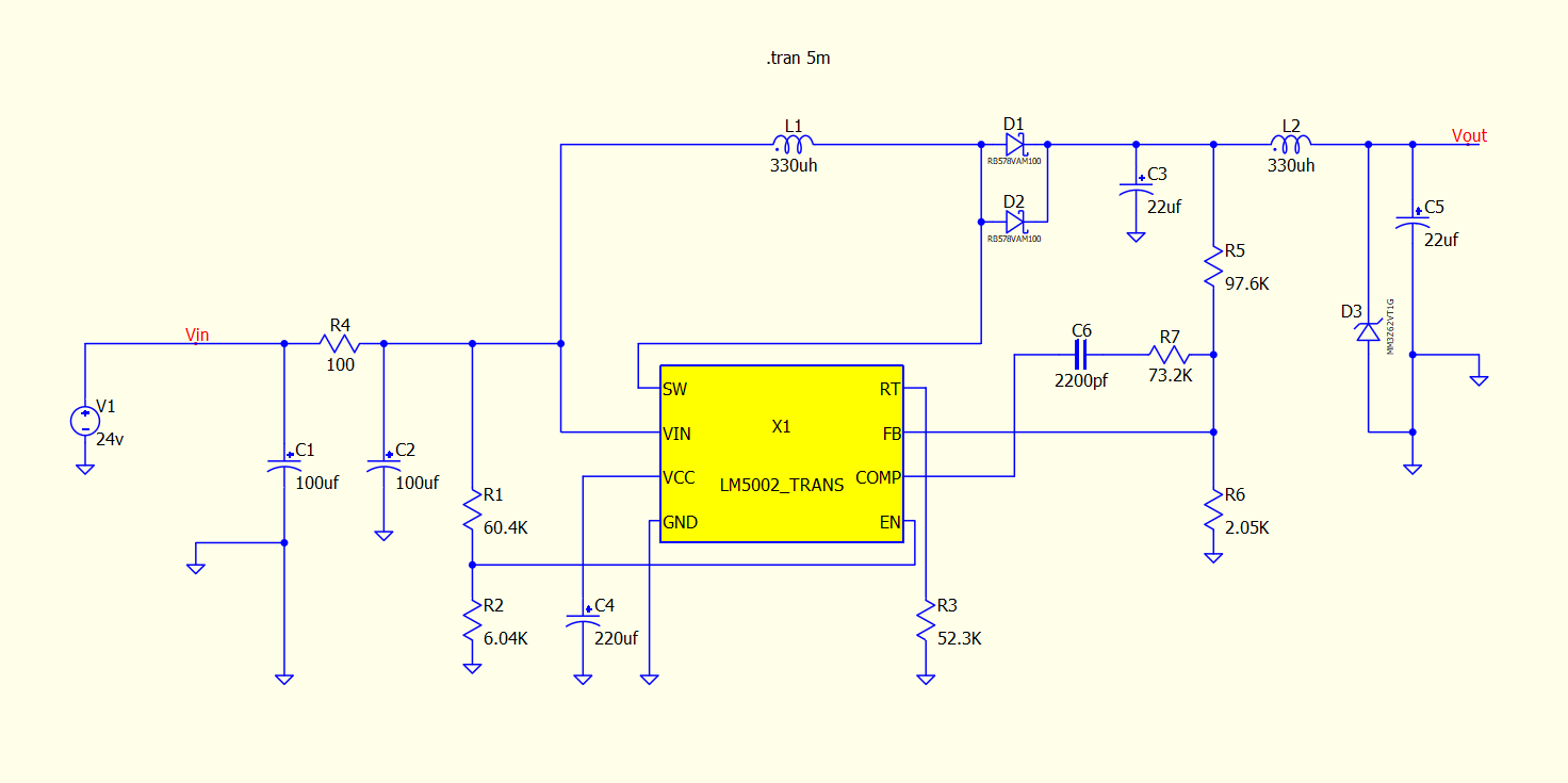
Fellow Spicers. I am trying to test a design of a dc to dc boost converter using the LM5002 switch mode voltage regulator. I obtained the spice model from Mouser. However, when I tried to run a transient analysis, it gave me a fatal error. It wants me to input values for something. I have never used a subckt nested IC part before. I am just a stupid beginner. If someone would be so kind to find out how I can get this regulator to run, that would really be helpful.
The issue is that Qspice doesn’t accept the omission of VH in the switch model, and VH=0 must be assigned or an error will be returned. Therefore, modifications to several switch .models are required in LM5002_TRANS.lib.
for example .MODEL _S2_MOD vswitch VT=6V RON=1K ROFF=1MEG ← VH=0 is omitted
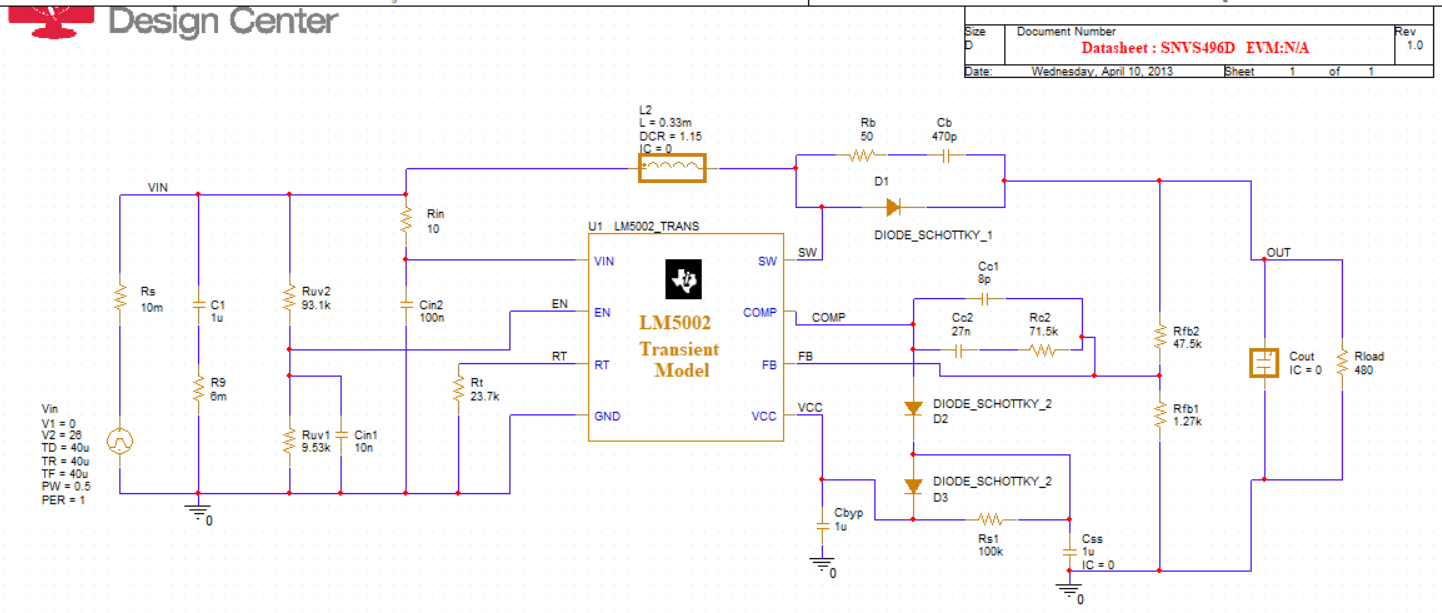
In addition, the TI model is a complex behavioral model, and you may encounter errors easily. My recommendation is to directly replicate a functional demo from TI first. Here is a schematic that replicates its PSpice example for your reference. There are 4 demo schematics; I only replicated the Startup Page, and here with library file modified for Qspice
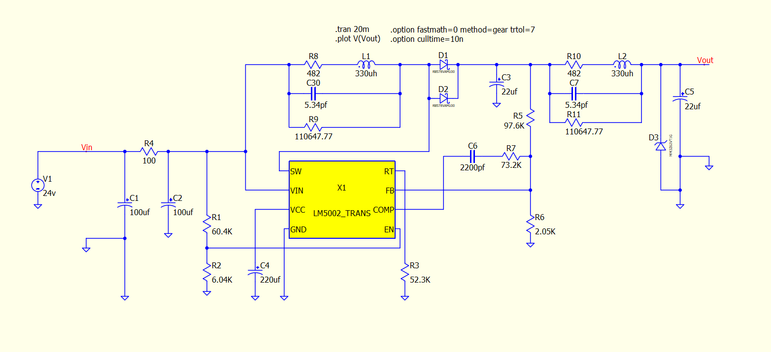
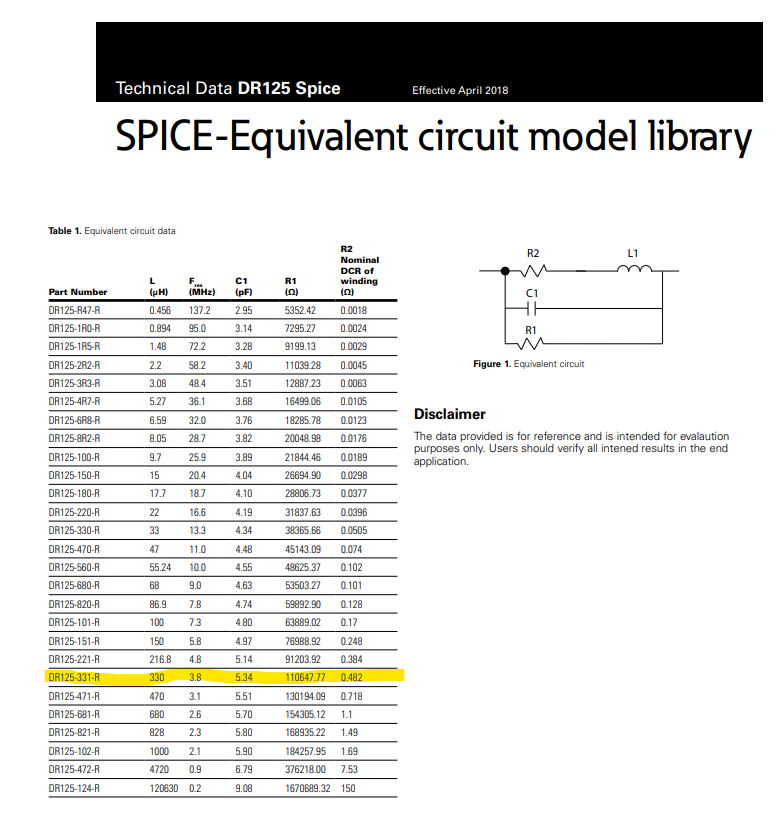
Yea that did it! Thanks. The new model works now without error. As for the schematic, I had a different problem. The inductors were not just normal inductors. I replaced them with the equivalent circuit suggested by the datasheet, and now it runs and simulates. Unfortunately it’s really slow, but the voltage rises. Here is a picture of the updated schematic that actually works.
Just curious, but is 20 mins too long to wait for a simulation? I think that is about how long it’s going to take, to see the voltage rise to 62 volts on the output.
In general, the TI spice model is painfully slow. The PSpice-TI version of the LM5002 Startup simulation took 723 seconds on my desktop, while the Qspice version took 110 seconds.
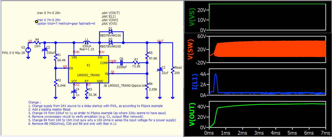
I made several changes to your simulation to ensure it runs according to the PSpice example. A comment section has been added to this schematic to list all changes, for example, the values of R4 and R8 don’t quite make sense to me.
Be very careful with complex integrated circuit models, as many of them are not designed to start simulation with a constant external voltage source (as they cannot provide .op solution). It is very common to see them using a PWL source to delay the supply voltage by setting it to 0V at 0s.