I’m getting the following error when trying to simulate my TL494 circuit in QSPICE:
Warning: library has a .ends without matching .subckt
Fatal error: Error: no ".ends" line.
All the .lib files I’m using do include proper .subckt and .ends statements, so I’m not sure what’s triggering this.
I’ve attached the following files for reference:
TL494_v2.qsch — my QSPICE schematic
tl494_v2.lib — my TL494 subcircuit model
LTC.lib — this file is included in tl494_v2.lib
UniversalOpamps2.lib , this file is included in tl494_v2.lib
I’m aware that there’s a working TL494 model by @bordodynov, but I’d still like to understand and develop my own version using the attached SPICE model.
If anyone could help identify what’s causing this .ends error (or how QSPICE parses nested .lib files differently), I’d really appreciate it.
Even if you solve that issue, these libraries (tl494_v2.lib and LTC.lib) will not work in Qspice. There are A-devices in them, and they are unique to LTspice. This is also the reason why @bordodynov and others worked on Qspice version.
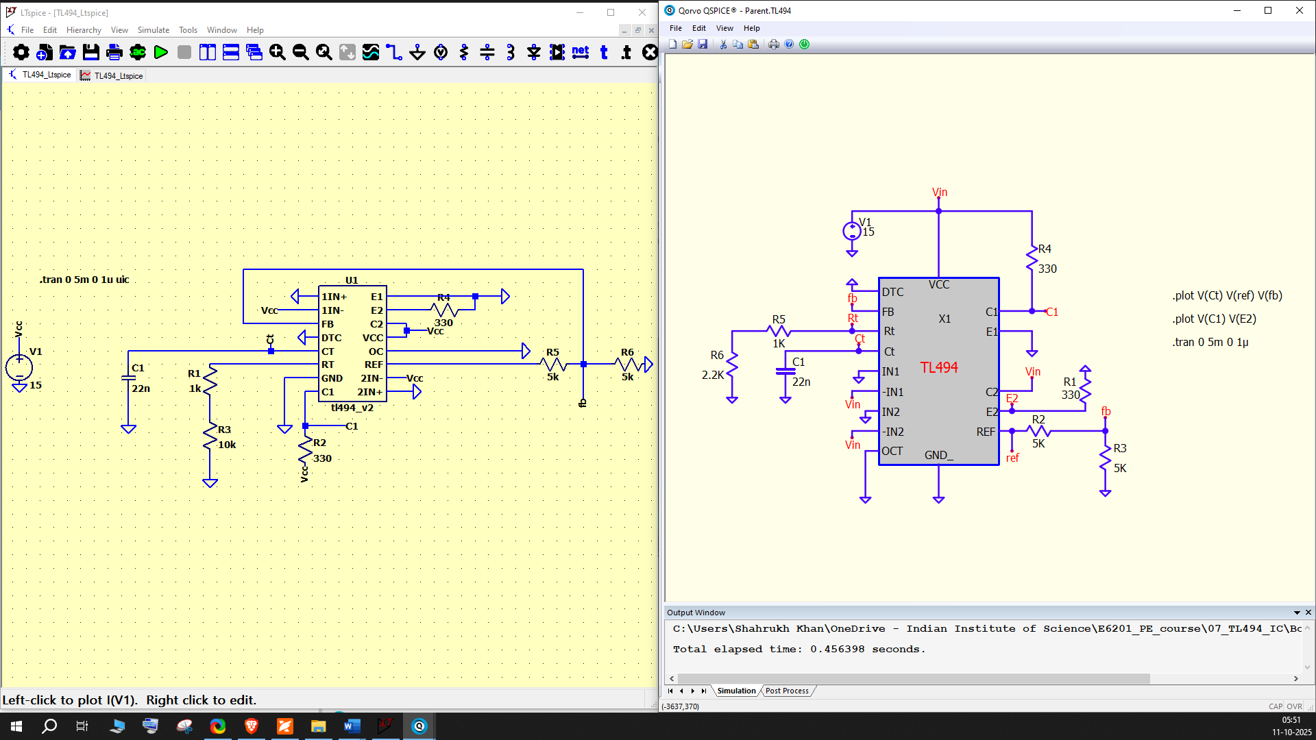
I am trying to simulate the TL494 PWM controller in both LTspice and QSPICE, using the same SPICE subcircuit and component values. However, I’m seeing a clear difference in the simulation results.
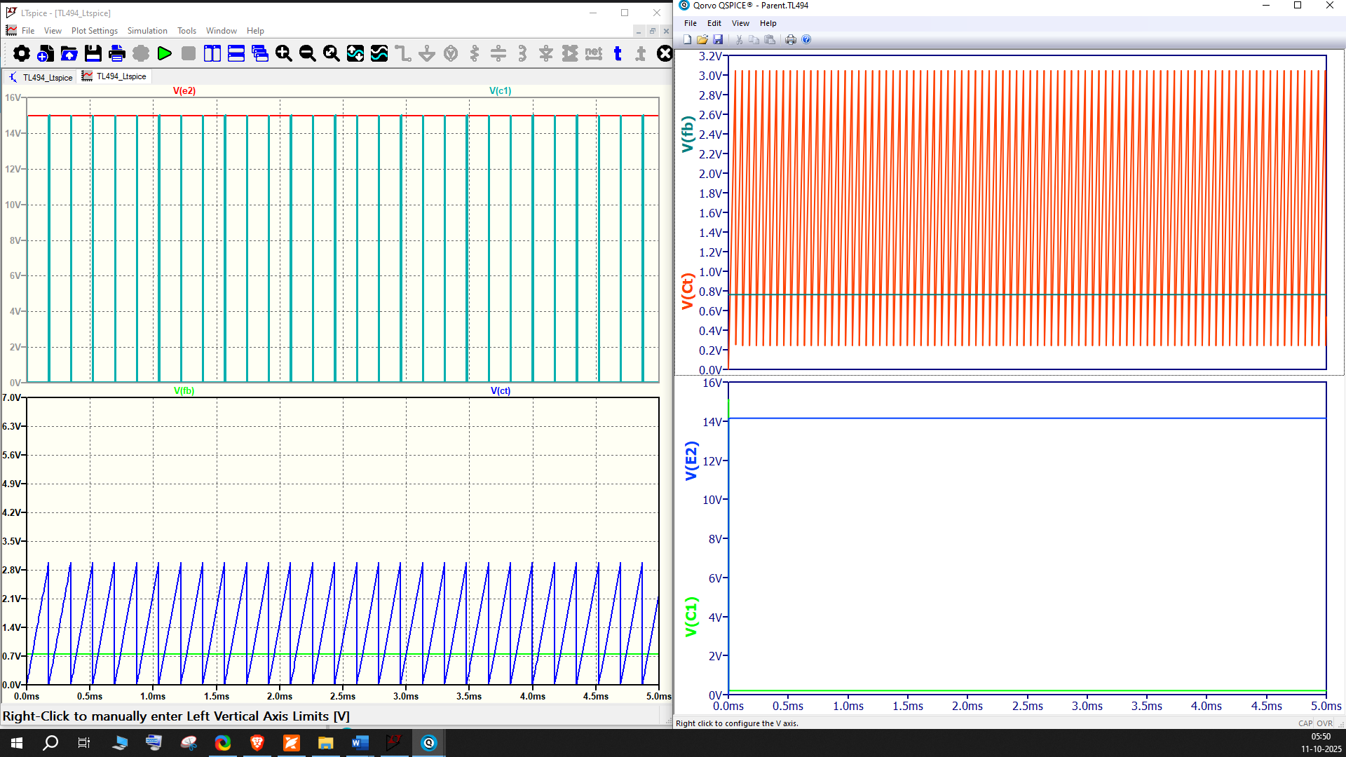
In LTspice, the waveforms (V(e2), V(c1), V(ct), and V(fb)) look correct — the CT pin shows a proper sawtooth ramp and outputs switch as expected.
In QSPICE, the same circuit produces very different waveforms. The C1 and E2 outputs are not matching with LTspice.
I’ve attached screenshots showing both results side by side for comparison.
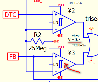
I am not familiar with TL494. Just read this model, the comparator ¥3, compare FB and sawtooth signal, with a Vt=0.7. This represents its +ve to -ve needs additional 0.7V to for output to set.
Some PWM ICs designed with an offset voltage, not sure if this is related to that. I think this model is from @bordodynov, he will have a better answer than mine. I just let you know what preventing this comparator to output a PWM signal in your current test signal level. If you reduce this Vt, you will start to see PWM output in your current setup.
I realize, according with another user experience, that in the modeling, an Axx device associated is not known by Qspice as with us intended specically to work with LTSpice.
Well, yes, Qspice will not recognize A-device as this is an Analog Device IP. However, equivalent devices are possible. Converting an A-device to a Qspice device is a very challenging task as it requires in-depth knowledge of both SPICE platforms and modeling. Currently, I have written a MATLAB routine to perform the conversion. I have obtained positive results in multiple conversion projects, and here is an example for the TL494, where the library is from Valentin Volodin https://valvol.xyz/models.php
A parsing problem from nested is often the cause of the.ends error.lib files. Compared to LTspice, QSPICE is more stringent. If you flatten the TL494 model into a single file only once, you’ll probably see the discrepancy right away.
A-devices are a larger problem. QSPICE does not support LTspice A-devices. Your CT ramp and C1/E2 outputs diverge because the TL494 won’t behave the same even if it compiles.
You must swap out the A-devices for supported behavioral elements if you want TL494 to match in QSPICE. If not, it will never match LTspice.
I have been trying to simulate a buck Converter with a 12 v DC source and , using both models published for tl494 but had been imposible to make feedback works properly, using The varios approach posted for this purposes.
I used The approach published by Texas, and other of users of qspice, I did My customized design but the pwm duty cycle don’t just change in a predictable way acording to tl494 performance.