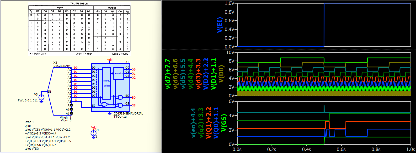
Is it possible to simulate an 8 bit to 3 bit priority encoder the same as a CD4532 with QSPICE?
This is the description lifted from the data sheet.
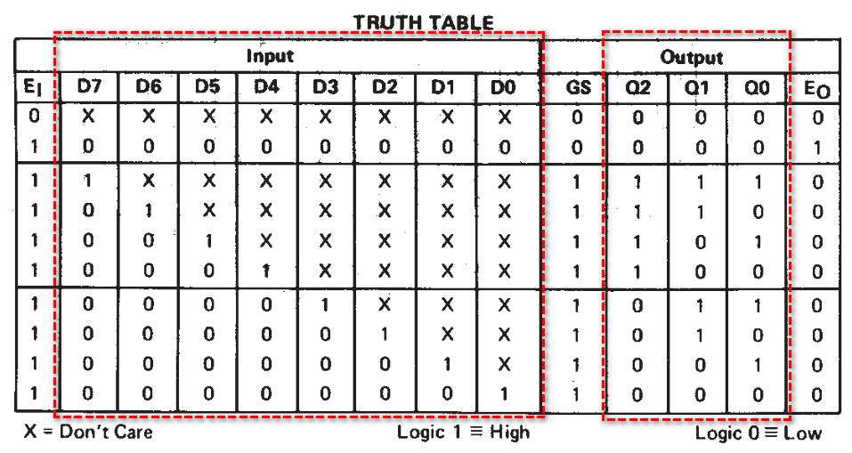
CD45328 consists of combination-
al logic that encodes the highest priority
input (D7-DO) to a 3-bit binary code. The
eight inputs, D7 through DO, each have an
assigned priority; D7 is the highest priority
and DO is the lowest. The priority encoder is
inhibited when the chip-enable input Ei is
low. When Ei is high, the binary representa-
tion of the highest priority input appears on
output lines Q2-Q0, and the group select
line GS is high to indicate that priority inputs
are present. The enable-out (Eo) is high
when no priority inputs are present. If any
one input is high, Eo is low and all cascaded
lower-order stages are disabled.
Maybe it can be done using verilog. Unfortunately I have no experience with verilog so i’m not sure where to start. Can anyone help?