- Qorvo DWM3000EVB (Digi-Key: 2312-DWM3000EVB-ND), qty 2
- Host MCU: ESP32 DevKitC x2, powered via USB (3.3V logic)
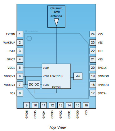
- Connection: GPIO jumper wires (not stacked shield) — RST=27, IRQ=34, SS=4
FIRMWARE
- Ranging mode: Single-Sided Two-Way Ranging (SS-TWR)
- Channel: 5 (6.5 GHz), Preamble: DWT_PLEN_128, PAC: DWT_PAC8, Preamble code: 9
- Data rate: DWT_BR_6M8, SFD: non-standard, STS: disabled
- Antenna delay: TX=16385, RX=16385 (both boards, uncalibrated default)
- Initiator: poll-TX to resp-RX delay = 240 us, RX timeout = 400 us
- Responder: poll-RX to resp-TX delay = 650 us
- Post-processing: two-point linear calibration (raw - 0.0622) / 0.8078, 7-sample median filter
FULL CODE
— INITIATOR —
#include “dw3000.h”

#define APP_NAME “SS TWR INIT v1.0”
#define SERIAL_BAUD 115200

const uint8_t PIN_RST = 27;
const uint8_t PIN_IRQ = 34;
const uint8_t PIN_SS = 4;

static dwt_config_t config = {
5,               /\* Channel number. */
DWT_PLEN_128,    /* Preamble length. Used in TX only. */
DWT_PAC8,        /* Preamble acquisition chunk size. Used in RX only. */
9,               /* TX preamble code. Used in TX only. */
9,               /* RX preamble code. Used in RX only. */
1,               /* 0 to use standard 8 symbol SFD, 1 = non-standard 8 symbol */
DWT_BR_6M8,      /* Data rate. */
DWT_PHRMODE_STD, /* PHY header mode. */
DWT_PHRRATE_STD, /* PHY header rate. */
(129 + 8 - 8),   /* SFD timeout \*/
DWT_STS_MODE_OFF,
DWT_STS_LEN_64,
DWT_PDOA_M0
};

#define RNG_DELAY_MS 1000
#define TX_ANT_DLY 16385
#define RX_ANT_DLY 16385

static uint8_t tx_poll_msg[ ] = {0x41, 0x88, 0, 0xCA, 0xDE, ‘W’, ‘A’, ‘V’, ‘E’, 0xE0, 0, 0};
static uint8_t rx_resp_msg[ ] = {0x41, 0x88, 0, 0xCA, 0xDE, ‘V’, ‘E’, ‘W’, ‘A’, 0xE1, 0, 0, 0, 0, 0, 0, 0, 0, 0, 0};

#define ALL_MSG_COMMON_LEN 10
#define ALL_MSG_SN_IDX 2
#define RESP_MSG_POLL_RX_TS_IDX 10
#define RESP_MSG_RESP_TX_TS_IDX 14
#define RESP_MSG_TS_LEN 4

static uint8_t frame_seq_nb = 0;
#define RX_BUF_LEN 20
static uint8_t rx_buffer\[RX_BUF_LEN\];
static uint32_t status_reg = 0;

#define POLL_TX_TO_RESP_RX_DLY_UUS 240
#define RESP_RX_TIMEOUT_UUS 400

static double tof;
static double distance;

static unsigned long success_count = 0;
static unsigned long timeout_count = 0;
static unsigned long error_count = 0;

extern dwt_txconfig_t txconfig_options;

void setup() {
Serial.begin(SERIAL_BAUD);
while (!Serial) { delay(10); }
delay(1000);


spiBegin(PIN_IRQ, PIN_RST);
spiSelect(PIN_SS);
delay(2);

while (!dwt_checkidlerc()) {
    Serial.println("IDLE FAILED");
    while (1);
}

if (dwt_initialise(DWT_DW_INIT) == DWT_ERROR) {
    Serial.println("INIT FAILED");
    while (1);
}

dwt_setleds(DWT_LEDS_ENABLE | DWT_LEDS_INIT_BLINK);

if (dwt_configure(&config)) {
    Serial.println("CONFIG FAILED");
    while (1);
}

dwt_configuretxrf(&txconfig_options);
dwt_setrxantennadelay(RX_ANT_DLY);
dwt_settxantennadelay(TX_ANT_DLY);
dwt_setrxaftertxdelay(POLL_TX_TO_RESP_RX_DLY_UUS);
dwt_setrxtimeout(RESP_RX_TIMEOUT_UUS);
dwt_setlnapamode(DWT_LNA_ENABLE | DWT_PA_ENABLE);
}

void loop() {
tx_poll_msg\[ALL_MSG_SN_IDX\] = frame_seq_nb;
dwt_write32bitreg(SYS_STATUS_ID, SYS_STATUS_TXFRS_BIT_MASK);
dwt_writetxdata(sizeof(tx_poll_msg), tx_poll_msg, 0);
dwt_writetxfctrl(sizeof(tx_poll_msg), 0, 1);
dwt_starttx(DWT_START_TX_IMMEDIATE | DWT_RESPONSE_EXPECTED);

while (!((status_reg = dwt_read32bitreg(SYS_STATUS_ID)) &
         (SYS_STATUS_RXFCG_BIT_MASK | SYS_STATUS_ALL_RX_TO | SYS_STATUS_ALL_RX_ERR)));

frame_seq_nb++;

if (status_reg & SYS_STATUS_RXFCG_BIT_MASK) {
    dwt_write32bitreg(SYS_STATUS_ID, SYS_STATUS_RXFCG_BIT_MASK);

    uint32_t frame_len = dwt_read32bitreg(RX_FINFO_ID) & RXFLEN_MASK;
    if (frame_len <= sizeof(rx_buffer)) {
        dwt_readrxdata(rx_buffer, frame_len, 0);

        rx_buffer[ALL_MSG_SN_IDX] = 0;
        if (memcmp(rx_buffer, rx_resp_msg, ALL_MSG_COMMON_LEN) == 0) {

            uint32_t poll_tx_ts, resp_rx_ts, poll_rx_ts, resp_tx_ts;
            int32_t rtd_init, rtd_resp;
            float clockOffsetRatio;

            // 32-bit local timestamps
            poll_tx_ts = dwt_readtxtimestamplo32();
            resp_rx_ts = dwt_readrxtimestamplo32();
            clockOffsetRatio = ((float)dwt_readclockoffset()) / (uint32_t)(1 << 26);

            // Remote timestamps from response payload (also 32-bit, via resp_msg_get_ts)
            resp_msg_get_ts(&rx_buffer[RESP_MSG_POLL_RX_TS_IDX], &poll_rx_ts);
            resp_msg_get_ts(&rx_buffer[RESP_MSG_RESP_TX_TS_IDX], &resp_tx_ts);

            rtd_init = resp_rx_ts - poll_tx_ts;
            rtd_resp = resp_tx_ts - poll_rx_ts;

            tof = ((rtd_init - rtd_resp * (1 - clockOffsetRatio)) / 2.0) * DWT_TIME_UNITS;
            distance = tof * SPEED_OF_LIGHT;

            Serial.print("DISTANCE: ");
            Serial.print(distance, 2);
            Serial.println(" m");

            success_count++;
        }
    }
} else {
    dwt_write32bitreg(SYS_STATUS_ID, SYS_STATUS_ALL_RX_TO | SYS_STATUS_ALL_RX_ERR);
    if (status_reg & SYS_STATUS_ALL_RX_TO) timeout_count++;
    if (status_reg & SYS_STATUS_ALL_RX_ERR) error_count++;
}

delay(RNG_DELAY_MS);
}
— RESPONDER —
#include “dw3000.h”

#define APP_NAME “SS TWR RESP v1.0”
#define SERIAL_BAUD 115200

const uint8_t PIN_RST = 27;
const uint8_t PIN_IRQ = 34;
const uint8_t PIN_SS  = 4;

static dwt_config_t config = {
5,
DWT_PLEN_128,
DWT_PAC8,
9,
9,
1,
DWT_BR_6M8,
DWT_PHRMODE_STD,
DWT_PHRRATE_STD,
(129 + 8 - 8),
DWT_STS_MODE_OFF,
DWT_STS_LEN_64,
DWT_PDOA_M0
};

#define TX_ANT_DLY 16385
#define RX_ANT_DLY 16385

// Note: responder reply delay is 650 us; initiator RX window closes at 240+400=640 us
#define POLL_RX_TO_RESP_TX_DLY_UUS 650

static uint8_t rx_poll_msg[ ] = {0x41, 0x88, 0, 0xCA, 0xDE, ‘W’, ‘A’, ‘V’, ‘E’, 0xE0, 0, 0};
static uint8_t tx_resp_msg[ ] = {0x41, 0x88, 0, 0xCA, 0xDE, ‘V’, ‘E’, ‘W’, ‘A’, 0xE1, 0, 0, 0, 0, 0, 0, 0, 0, 0, 0};

#define ALL_MSG_COMMON_LEN      10
#define ALL_MSG_SN_IDX          2
#define RESP_MSG_POLL_RX_TS_IDX 10
#define RESP_MSG_RESP_TX_TS_IDX 14
#define RESP_MSG_TS_LEN         4

static uint8_t  frame_seq_nb = 0;
#define RX_BUF_LEN 12
static uint8_t  rx_buffer\[RX_BUF_LEN\];
static uint32_t status_reg = 0;

static uint64_t poll_rx_ts;
static uint64_t resp_tx_ts;

extern dwt_txconfig_t txconfig_options;

void setup() {
Serial.begin(SERIAL_BAUD);
while (!Serial) { delay(10); }
delay(1000);

spiBegin(PIN_IRQ, PIN_RST);
spiSelect(PIN_SS);
delay(2);

while (!dwt_checkidlerc()) {
    Serial.println("IDLE FAILED");
    while (1);
}

if (dwt_initialise(DWT_DW_INIT) == DWT_ERROR) {
    Serial.println("INIT FAILED");
    while (1);
}

dwt_setleds(DWT_LEDS_ENABLE | DWT_LEDS_INIT_BLINK);

if (dwt_configure(&config)) {
    Serial.println("CONFIG FAILED");
    while (1);
}

dwt_configuretxrf(&txconfig_options);
dwt_setrxantennadelay(RX_ANT_DLY);
dwt_settxantennadelay(TX_ANT_DLY);
dwt_setlnapamode(DWT_LNA_ENABLE | DWT_PA_ENABLE);

}

void loop() {
dwt_write32bitreg(SYS_STATUS_ID,
SYS_STATUS_RXFCG_BIT_MASK |
SYS_STATUS_ALL_RX_TO       |
SYS_STATUS_ALL_RX_ERR);


dwt_rxenable(DWT_START_RX_IMMEDIATE);

while (!((status_reg = dwt_read32bitreg(SYS_STATUS_ID)) &
         (SYS_STATUS_RXFCG_BIT_MASK | SYS_STATUS_ALL_RX_TO | SYS_STATUS_ALL_RX_ERR)));

if (status_reg & SYS_STATUS_RXFCG_BIT_MASK) {
    dwt_write32bitreg(SYS_STATUS_ID, SYS_STATUS_RXFCG_BIT_MASK);

    uint32_t frame_len = dwt_read32bitreg(RX_FINFO_ID) & RXFLEN_MASK;
    if (frame_len <= sizeof(rx_buffer)) {
        dwt_readrxdata(rx_buffer, frame_len, 0);

        rx_buffer[ALL_MSG_SN_IDX] = 0;
        if (memcmp(rx_buffer, rx_poll_msg, ALL_MSG_COMMON_LEN) == 0) {

            // TIME CRITICAL SECTION — no Serial prints until after dwt_starttx()
            poll_rx_ts = get_rx_timestamp_u64();

            uint32_t resp_tx_time =
                (poll_rx_ts + (POLL_RX_TO_RESP_TX_DLY_UUS * UUS_TO_DWT_TIME)) >> 8;

            dwt_setdelayedtrxtime(resp_tx_time);

            // Predicted TX timestamp written into payload
            resp_tx_ts = (((uint64_t)(resp_tx_time & 0xFFFFFFFEUL)) << 8) + TX_ANT_DLY;

            resp_msg_set_ts(&tx_resp_msg[RESP_MSG_POLL_RX_TS_IDX], poll_rx_ts);
            resp_msg_set_ts(&tx_resp_msg[RESP_MSG_RESP_TX_TS_IDX], resp_tx_ts);

            tx_resp_msg[ALL_MSG_SN_IDX] = frame_seq_nb;
            frame_seq_nb++;

            dwt_writetxdata(sizeof(tx_resp_msg), tx_resp_msg, 0);
            dwt_writetxfctrl(sizeof(tx_resp_msg), 0, 1);
            int tx_result = dwt_starttx(DWT_START_TX_DELAYED);
            // END TIME CRITICAL SECTION

            if (tx_result == DWT_SUCCESS) {
                while (!(dwt_read32bitreg(SYS_STATUS_ID) & SYS_STATUS_TXFRS_BIT_MASK));
                dwt_write32bitreg(SYS_STATUS_ID, SYS_STATUS_TXFRS_BIT_MASK);
                Serial.println("Response sent OK");
            } else {
                Serial.println("ERROR: Delayed TX failed (too late)");
                dwt_write32bitreg(SYS_STATUS_ID, SYS_STATUS_ALL_RX_TO | SYS_STATUS_ALL_RX_ERR);
            }
        }
    }
} else {
    dwt_write32bitreg(SYS_STATUS_ID, SYS_STATUS_ALL_RX_TO | SYS_STATUS_ALL_RX_ERR);
}
}
PROBLEM
We are getting inaccurate and highly variable readings both indoors and outdoors. After applying a two-point linear calibration and a 7-sample median filter, accuracy is still poor — especially at close range and beyond ~5 m.
Raw (uncalibrated) measurements at known distances, boards stationary, face-to-face:
Actual    Low      Mid      High     Spread
0 cm      0.43 m   0.45 m   0.47 m   0.04 m
10 cm    -0.05 m   0.10 m   0.24 m   0.29 m
1 m       0.80 m   0.87 m   0.89 m   0.09 m
10 m      7.53 m   8.14 m   8.76 m   1.23 m
Key observations:
- At 10 cm, readings are completely unreliable (-0.05 m to +0.24 m, a 0.29 m spread)
- At 1 m, spread is ~9 cm even after filtering
- At 10 m indoors, spread reaches 1.23 m
- Behavior is similar indoors and outdoors, so multipath alone does not seem to be the cause
- Increasing the median filter from 7 to 32 samples produced no meaningful improvement,
suggesting the underlying measurements themselves are noisy rather than occasional outlier spikes
WHAT WE HAVE TRIED
- Verified SPI — dwt_readdevid() returns 0xDECA0302 on both boards
- Two-point linear calibration from 1 m and 10 m reference points
- 7-sample and 32-sample median filter — no meaningful difference in accuracy or spread
- Tested indoors and outdoors — similarly variable in both environments
- Varied antenna orientation (face-to-face, side-by-side, angled) — no consistent improvement
- Increased responder reply delay to 650 us to reduce delayed TX failures
- Enabled LNA/PA on both boards via dwt_setlnapamode(DWT_LNA_ENABLE | DWT_PA_ENABLE)
QUESTIONS
- TIMING WINDOW MISMATCH
The initiator opens its RX window 240 us after sending the poll and keeps it open for
400 us, so the window closes at 640 us. The responder is set to reply at 650 us — 10 us
after the initiator’s window has already closed. Is this the cause of most of our failed
or noisy exchanges? What is the correct relationship between POLL_TX_TO_RESP_RX_DLY_UUS,
RESP_RX_TIMEOUT_UUS, and POLL_RX_TO_RESP_TX_DLY_UUS? - TIMESTAMP ASYMMETRY
The initiator reads timestamps with dwt_readtxtimestamplo32() and dwt_readrxtimestamplo32()
(32-bit lower half of the 40-bit counter). The responder reads with get_rx_timestamp_u64()
(full 64-bit). The original Qorvo example note says 32-bit is safe because the round trip
is always under 2^32 device time units (~67 ms). But the remote timestamps embedded in the
response payload are written by resp_msg_set_ts() from the full 64-bit value and then read
back by resp_msg_get_ts() into a 32-bit variable on the initiator side — could truncation
there be causing ranging error? Or is the mixed 32/64-bit usage across the two devices
introducing a subtler inconsistency? - ANTENNA DELAY CALIBRATION
We are using TX=RX=16385 which is the uncalibrated default. The 0 cm reading of ~0.45 m
confirms a significant fixed offset. Is there a Qorvo-recommended two-point calibration
procedure for DWM3000EVB, or a published/community-confirmed starting value for channel 5
/ 6.8 Mbps / preamble code 9? - SS-TWR ACCURACY CEILING
Once timing and timestamp issues are resolved, is SS-TWR with clock-offset correction
realistically capable of ~10 cm accuracy at 1-10 m on DW3000, or is DS-TWR required to
get there? The spread we are seeing persists even with a 32-sample filter, which suggests
something more fundamental than multipath or occasional outliers.
In short, is it possible to achieve centimeter accuracy for the distance between two DWM3000EVB + ESP32 using the setup that we have here or is it impractical to get our readings down to the nearest centimeter?
Any guidance is greatly appreciated. Thank you!