I have been using DWM3000 for a while. I need to develop a system which measures the distance between two beacons with a 10 cm of accuracy in a short range, less than 1 meter.
For measuring, I send four messages. First, one from starter to repeater, then repeater, programs in DWM3000, sending another one to starter after 1.5ms. After receiving it, starter do the same and sends another one. And the repeater repeat this process again and sends final one with its timestamps.
Then the stater computes the distance. It computes three time differences by using: 1st and 2nd message, 2nd and 3rd one and 3rd and 4th message.
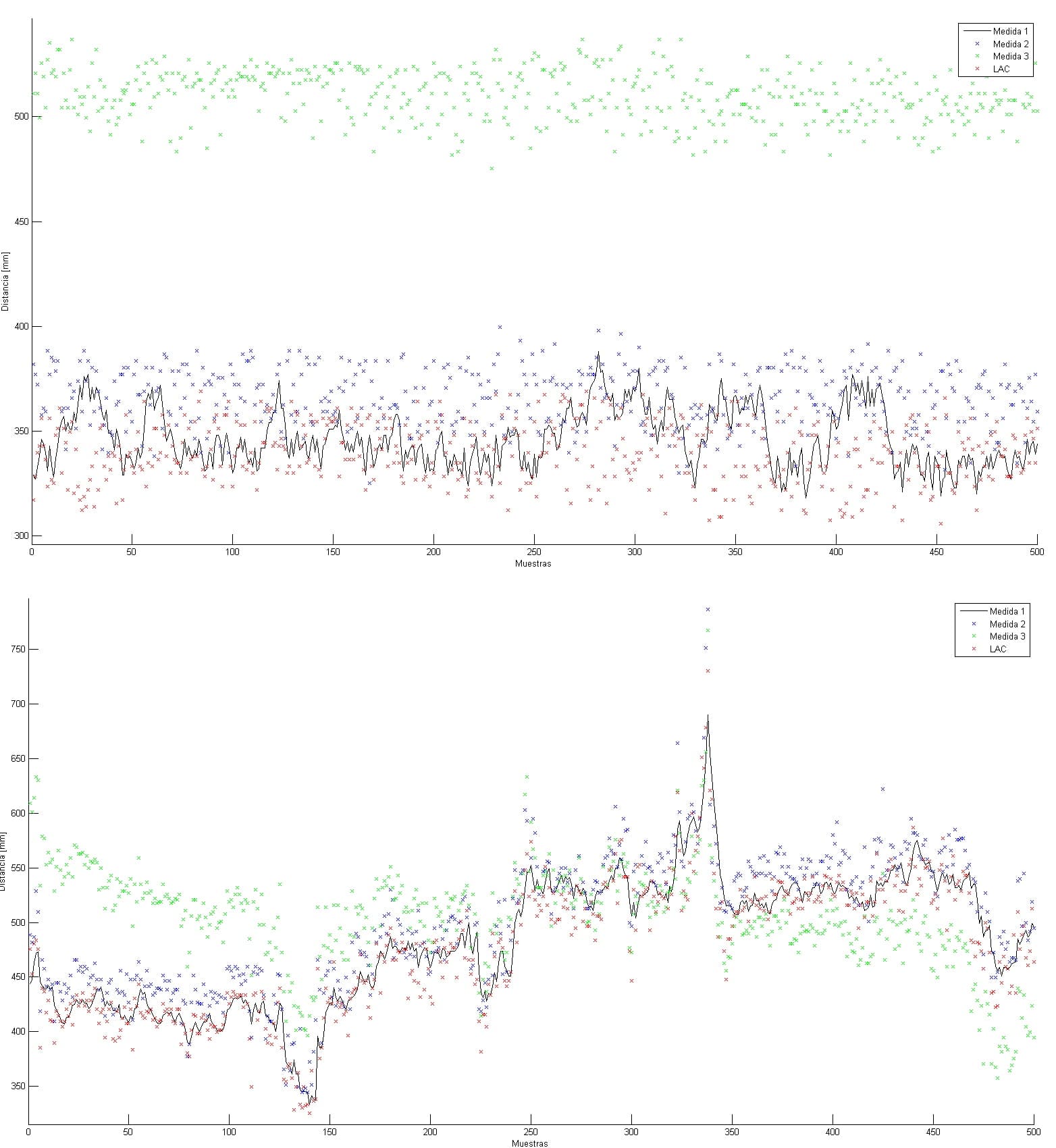
I have notice that a drift in the data appears, although both devices are static. I upload a couple of photos to explain it better. In the photo, x-axis represents the number of consecutive samples taken (500 samples) between samples there is a delay of 500 ms. The y-axis represents distance in mm. To calculate the distance, previously I have done a calibration process to calculate a experimental regresssion between ticks of DWM3000 and distance of both devices.
The x markers show distance calculated by each couple of messages.
In the upper graph of the photo, it can be seen distance measurement when both devices are over a table in front of each other. And in the lower one, one devices is located over a table and the other is in the wrist. In both cases real distance is 250mm.
As you can see, in the first one there is an offset of 50mm, which is quite reasonable, plus some noise. In the second one, there is an offset which is varies along time and it is quite high, as large as measured distance.
I have two questions:
Which causes the drift in the second case if both devices are static? And if is it possible to minimize it?
Which RF configuration is more suitable for short range distance measurement
Why did you “calculate a experimental regresssion between ticks of DWM3000 and distance of both devices.”
Each tick represents a known period of time, roughly 15ps. Once you know the number of ticks it is a case of converting to time by multiplying by the period and then multiplying by the speed of light to get distance. You will need to correct for antenna delays but that will be a constant.
By doing a two way range you can correct for differences in clock speeds on the two devices. However that calculation does assume that the clocks are stable during the measurement period, the longer your measurement period the less this is true. For the ranges you are looking at it’s possible to perform the entire 4 message exchange in under 1ms, your 1.5ms between messages is far longer than it needs to be.
A system like this you should be able to get the standard deviation of measurements down to the 3-5 cm region.
What is your antenna gain pattern like? In the second case is the antenna orientation the same as in the first? Could something be causing the signal level to drop lower and so making it more error prone? If so does boosting the power have any effect?
You say it’s static but you also say it’s on a wrist and measured over a reasonable time period. How static is static? If you have line of sight small movements shouldn’t have much impact but potentially if they are changing antenna orientation that could impact signal levels which in turn can have a 10-15 cm impact on range. Due to the inverse square law this has the most impact at short ranges.
Are you compensating for temperature and power level effects on range measurement? I’d expect these to be constant for a static situation and so add a constant offset not noise but always worth checking.
Thanks for the information. I will try to answer all you ask me.
I have read in your manual that actually the way to calculate distances is what you say. But, I am trying to validate this technology for our porpouses. So, for me it is more simple to do a linear regression than calculating antena delay, although it is the same at the end.
Regarding time between messages, i will try to short as much as i can. Unfortunatelly, I have no access to IRQ pin of DW3000 module so my aplication is polling through SPI the chip.
About the antenna patern, I am using DW3000 module and i try to follow all your recommendations. But I have no measured radiation pattern, so I cannot give you so much information.
Regarding distance measurement, static is pretty static in both cases, because the wrist is over the table and it does not move. But orientation, in the second case is turned 90º over the same place. So some offset could be introduce for this fact.
Finally, the room temperature where I test it was 24ºC which is quite close to 20ºC (temperature of factory calibration). So I do not commpesate this factor. The power supply is not comepessated either. But I realized I am supplying the chip at 3V through an LDO so I will try to compessate and check peak currents to know if this LDO is correctly chosen.
As soon as I do all tests, I will upload the information.
Hi, I have been working from a while in this issue.
I have reduced time between messages, but it has no effect. Then I tried to calibrate the PLL. In chapter 10, 4 point, of DW3000 user manual, it explains how to calibrate it, but at least it does not work. As it explains I do the following:
Set device in state IDLE_RC: reset AINTIT2IDLE, set FORCE2INIT, establish SYSCLK to 3, clearing FORCE2INIT, restoring SYSCLK to 0.
Set CAL_EN in PLL_CAL register and set AINTIT2IDLE.
Wait until PLL is locked. But it does not happen.
Have anyone any idea of where is the error?
In the same chapter says that channel 5 does not need any calibration. So I use it, and there is an improvement in the measure. It is more stabilish and there are not any tendency only noise which is expected.