I am developing an indoor positioning system for warehouse worker safety using the DWM3000 module (DW3110 IC) on a custom ESP32-S3 carrier board. I am experiencing significantly lower range and RSSI than
expected and would appreciate your guidance.
THE PROBLEM:
At 5 meters LOS I am measuring RSSI of approximately -90 dBm
Maximum usable range is limited to ~17 meters before tags lose connection with anchors
The system is extremely sensitive to any obstacle in the signal path
This is consistent across all 4 modules I have tested — not a single defective unit
Expected performance based on DWM3000 datasheet: 30–60 m LOS with similar configuration
RADIO CONFIGURATION:
Channel: 5 (6489.6 MHz)
Preamble length: 4096 symbols
Preamble code: 9
PAC size: 32
Data rate: 850 kbps
STS length: 128 symbols
SFD: Standard
TX Power register: 0xFEFEFEFE (verified via readback — see dump below)
REGISTER DUMP (read back after full init — addresses match write locations):
TX_POWER = 0xFEFEFEFE (near-maximum, coarse gain 7, fine gain 30)
RF_TX_CTRL2 = 0x1C071134 (correct for Channel 5)
RF_TX_CTRL1 LSB = 0x0E (correct for Channel 5)
DGC loaded from OTP (OTP_CFG bit 2 set)
Since all register values are correct, I believe the issue is related to my PCB antenna environment rather than firmware configuration.
HARDWARE DESIGN:
LDO: LDL1117S33R (3.3V, 1.2A capable) with decoupling capacitors at all DWM3000 power input pins
PCB: 4-layer stackup, DWM3000 antenna positioned at board edge
Antenna keep-out: I followed the DWM3000 integration guide — no copper pour, ground plane clearance, and no traces within the exclusion zone around the chip antenna
TX power is confirmed at maximum (register readback verified)
RF_TX_CTRL2 is correctly set for Channel 5 (register readback verified)
SPI communication is stable (DEV_ID reads correctly, no errors)
DGC is loading from OTP correctly
Multiple modules tested — all show identical behavior
Issue is consistent regardless of which anchor/tag pair is tested
MY QUESTIONS:
Given that all registers are correctly configured, is -90 dBm at 5 m consistent with antenna detuning due to PCB layout? What specific layout issues should I look for?
Are there known sensitivities with the DWM3000 chip antenna regarding ground plane proximity on inner layers, or board thickness requirements?
Would you be able to review my Gerber files and identify any keep-out or clearance issues?
Is there a recommended way to verify antenna return loss without a VNA, or any self-test I can run in firmware?
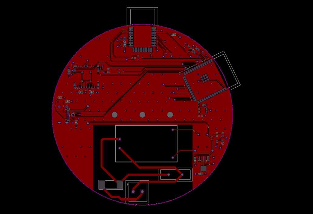
I have attached the Gerber files for the carrier board.
Thank you for your time. Reliable range is critical for this warehouse safety application and any guidance would be greatly appreciated.
Not from qorvo but I’ve found better range performance using the decawave 16 bit SFD rather than the IEEE one.
Do you need to use encryption? Try turning the STS mode off (you don’t explicitly say you have it on but you give a length which implies you are using it).
Ultimately the best way we found to get more range out of the system was to not use the module and put a better antenna on the system. But that is then significantly more work.
Thank you — this was extremely helpful and you were right on all three points.
DecaWave 16-bit SFD: Already had this set (SFD_TYPE=2 in CHAN_CTRL). Good to have confirmation it’s the right choice.
STS mode: This was the big one. I dug into my SYS_CFG register value (0x188) and realized bit 3 was set — CP_SPC=01, meaning STS SP1 was active with 128 symbols. The math makes it
obvious now: my preamble has 4096 symbols of integration gain, but the STS only has 128 symbols. That’s roughly 15 dB less processing gain on the STS correlator compared to the preamble
detector. So at long range, the preamble detects fine, the data decodes fine, but the STS correlation fails and the chip rejects the entire frame. I was effectively capping my range at
whatever distance the 128-symbol STS could survive — not what the actual radio link could achieve. I’ve disabled STS (changed SYS_CFG to 0x180 and removed the STS_CFG write) and will
test shortly. For a private warehouse man-down safety system, anti-spoofing isn’t a concern, so there’s no reason to keep it enabled at the cost of range.
Better antenna: I’m already looking into a PCB redesign using the bare DW3110 chip with a Qorvo QM14068 external LNA and a Taoglas UWCCP.01 patch antenna (6.5 dBi). The link budget math
suggests roughly +11 dB improvement on the receive side. But I wanted to exhaust the firmware-side optimizations first before committing to new hardware, so your STS suggestion came at
the perfect time.
Will report back with range test results after the STS change. Thanks again.
Depending on the requirements and the RF environment you may want to consider the DW1000 rather than the 3000. They both support channel 5, you lose channel 9 support but gain 4 different ~4 GHz channel options. The path loss on those frequencies is less which buys you a bit of range. It also supports a lower data rate option. Terrible for update rate or large packets but for short packets it should give you a bit more range (In theory, I’ve never personally tested below the 850 kb/s rate).
Will you need to get this approval tested? If so be careful of antennas with directional gain. The transmit power limit is as measured in the direction with the highest strength so a directional antenna means you have to turn the power down. You still get a benefit if the two antennas are correctly aligned but if they are misaligned it doesn’t take much to make things worse than using omnis. Although if this is for something to go on a person there is no harm in directing as much energy as possible away from their body, that part of your signal power isn’t going to help you anyway.
In terms of the board I can’t see any obvious issues. Personally I would have tried to put the ESP antenna further away from the DW3000 antenna but that is more due to paranoia rather than any hard reasons.
Why do you set the preamble length to 4096 symbols?
Set plen to 128, sts 128;
Or even 64/64.
Datarate - why you use 850? experiment with datarates 6.8Mbps for both payload and PHR.
Why i am advising of the above? In your config the length of the frame is >4ms, you cannot benefit any Tx power increase on gating gain.
The new RF config would let you benefit from higher TX thanks shorter frames length <<1ms, so your link budget would increase
Thanks for the great advice! I’ve implemented the changes and will test shortly.
For context — I recently maxed out the TX power (0xFFFFFFFF) and was able to achieve 43 meters in open air with the
old config (PREAMBLE_4096, 850kbps, PAC32). RSSI was -103 dBm at that distance, which is basically the module’s limit
with the long frame.
I’ve now switched to the short-frame config you suggested:
Preamble: 4096 → 128
Data Rate: 850kbps → 6.8Mbps (both payload and PHR)
PAC: PAC32 → PAC8
STS: 128 → 64 symbols
SFD: DW-16 → DW-8
SFD Timeout: 4113 → 137
Frame duration should now be well under 1ms, which should unlock the TX gating gain. I’ll flash all boards (tag + 3
anchors) with these settings and report back with the results.
If you do not care of regulatory -41.3 dBm/MHz spectral density Tx power, then it does not make sense to shorten the frame length: chip cannot transmit over 0xFFFFFFFF. To use the Tx gating gain you should set Tx power yourself, chip does not adjust the Tx power “automatically”, I think. but there could be some driver functions to adjust the Tx power of current frame vs calibrated one.