Good day.
I have never dealt with such devices before and could not find information anywhere, so I decided to ask you. How many devices can be connected to each other at the same time? I want to have one master and several slaves…
I know that with nRF24L01 you can connect 6 devices at the same time…
Depending on how you want to define things the answer is somewhere between 1 and infinity.
Radio is inherently a broadcast system. One device transmits, any other device in range can listen to that transmission. In fact the hard part is often stopping others from listening when you don’t want them to. So in one direction there is no real limit to how many devices can be listening.
As soon as you get into two way communication it gets more complicated, you need to define how to avoid different devices talking on top of each other. That isn’t purely set by the physical radio, it’s also defined by the protocol used which is controlled by software.
Things like bluetooth and wifi have very rigidly defined protocols that set those limits. UWB doesn’t. If you want to say interact with an iPhone then you need to follow the protocol that apple have used. Or if you want to use the free out of the box positioning system that Qorvo supply then you need to live with the restrictions that imposes. But if you are only talking to your own equipment and write your own firmware then you can define the protocol in any way you see fit.
There are some fundamental restrictions, only one device can be transmitting at a time and messages take a certain length of time to transmit (which varies depending on their length and other factors). That limits the maximum number of messages that can be sent each second without running into issues.
How close you get to that maximum and how many devices listen for and make use of the information within those messages is up to the protocol. Which you can define.
To give you an example the system I created will track up to 5 tags at a time and output their positions at 100 Hz. Each tag will measure ranges to up to 12 anchors. A total of up to 200 anchors can be installed with the system picking the best 12 for each tag, a total of 2400 ranges per second. So in theory 60 simultaneous “connections” with each tag connected to 12 anchors and each anchor connected to up to 5 tags. However in order to do this I had to compromise flexibility, all the tags need to be configured to know how many other tags are running at the same time. Not an issue for my application but a big issue for lots of uses.
If you were talking about the matrix method, when one transmits data through the other all the way to the final receiver, then I read a little about this type of data transmission but on the same nRF24L01. I agree that there can be many implementations of data transmission. I am interested in the maximum interaction of devices on a large area…
Here is a good example of Video.
The man tracked the movements between the columns. I am interested in the location (coordinates) of beacons on the field…
No I’m not talking about a matrix or mesh network. I’m talking about the fundamental basics of a radio. Unless you have a very fancy antenna a radio transmits in all directions, everything in range can pick up the transmissions simultaneously (give or take the travel time at the speed of light) if they are set to look for the correct thing.
To be honest that video is not a very good demo. He’s only implementing a very basic position system there, not controlling antenna orientation or polarisation and is putting the antennas close to surfaces that will change their performance. With that many uncontrolled effects and only a crude antenna delay calibration the performance is never going to be very good.
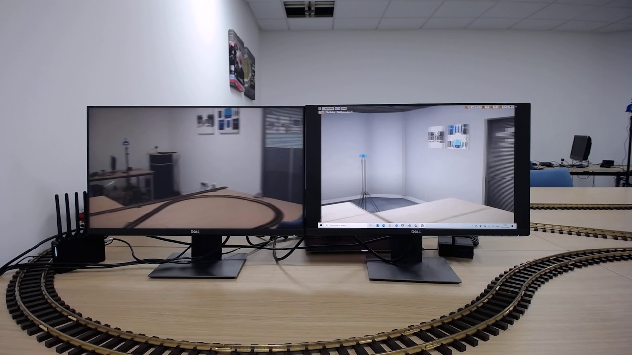
Take what he did but expand it to 3D and create a 3d model of the room you’re in.
Then attach a UWB tag to a physical camera. Use the UWB position of that tag to move a virtual camera around your 3d model.
Put the monitors showing the real camera output and the view from your virtual camera next to each other.
Do all that and you end up with a demo like this:
Now I understand what you mean. I want something a little different. Here is a site with a better example of Link.
I am interested in conditional coordinates relative to the receiver.
It turns out that you are saying that there are no restrictions on the number and everything is guaranteed by the protocol, right?
Yes. As I said multiple times it is all dependent on the protocol you use. The default is every device receives every transmision. What happens after that is up to you.
I have no idea what “conditional coordinates relative to the receiver” are. The receiver must know the anchor locations in advance. Without that information all that it would know is that it is at a known distance from an unknown location, which generally isn’t much use.
All calculated coordinates are going to be relative to those anchor locations, there is no absolute truth so it’s a coordinate system you pick relative to an arbitrary point you get to pick. Generally this will be this will be a cartesian x/y or x/y/z system relative to some fixed point in the covered area, the corner of the room or the location of the first anchor usually.
If you know the anchor locations in the room then once you’ve calculated the receiver location relative to the room calculating the anchors relative to the receiver would be trivial.
