Hi everyone,
I’ve run into a recurring issue while working with the DWM3000 UWB module on my custom PCB module to connect to an ESP32. I’ve successfully soldered and brought up a few DWM3000 chips, however out of 12 of them, 5 of them works well without issues. But out of the other 7, I notice 3 of them had a strange failure pattern.
After soldering a new DWM3000 chip:
- The module works normally for the first 2–3 minutes
- Then it suddenly stops functioning.
- On removing power and checking with a multimeter, I find that there’s now a short circuit between VCC and GND.
- This has happened with multiple chips, although not all. Some continue to work fine.
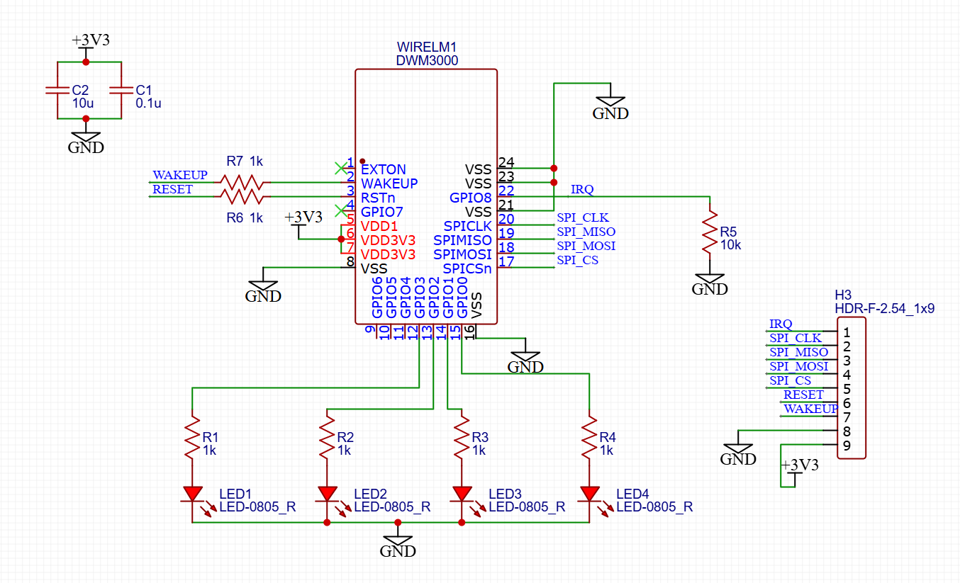
Attached below is the schematic used, i have soldered everything except for R3,R4, LED3 and LED4.
The code that I was using was the Makerfabs-ESP32-UWB-DW3000
ex_01a_simple_tx.ino example
(GitHub - Makerfabs/Makerfabs-ESP32-UWB-DW3000)
#include “dw3000.h”
#define APP_NAME “SIMPLE TX v1.1”
// connection pins
const uint8_t PIN_RST = 27; // reset pin
const uint8_t PIN_IRQ = 34; // irq pin
const uint8_t PIN_SS = 4; // spi select pin
/* Default communication configuration. We use default non-STS DW mode. /
static dwt_config_t config = {
5, / Channel number. /
DWT_PLEN_128, / Preamble length. Used in TX only. /
DWT_PAC8, / Preamble acquisition chunk size. Used in RX only. /
9, / TX preamble code. Used in TX only. /
9, / RX preamble code. Used in RX only. /
1, / 0 to use standard 8 symbol SFD, 1 to use non-standard 8 symbol, 2 for non-standard 16 symbol SFD and 3 for 4z 8 symbol SDF type /
DWT_BR_6M8, / Data rate. /
DWT_PHRMODE_STD, / PHY header mode. /
DWT_PHRRATE_STD, / PHY header rate. /
(129 + 8 - 8), / SFD timeout (preamble length + 1 + SFD length - PAC size). Used in RX only. /
DWT_STS_MODE_OFF,
DWT_STS_LEN_64, / STS length, see allowed values in Enum dwt_sts_lengths_e /
DWT_PDOA_M0 / PDOA mode off */
};
/* The frame sent in this example is an 802.15.4e standard blink. It is a 12-byte frame composed of the following fields:
-
- byte 0: frame type (0xC5 for a blink). -
- byte 1: sequence number, incremented for each new frame. -
- byte 2 -> 9: device ID, see NOTE 1 below.
/
static uint8_t tx_msg[] = {0xC5, 0, ‘D’, ‘E’, ‘C’, ‘A’, ‘W’, ‘A’, ‘V’, ‘E’};
/ Index to access to sequence number of the blink frame in the tx_msg array. */
#define BLINK_FRAME_SN_IDX 1
#define FRAME_LENGTH (sizeof(tx_msg) + FCS_LEN) // The real length that is going to be transmitted
/* Inter-frame delay period, in milliseconds. */
#define TX_DELAY_MS 500
extern dwt_txconfig_t txconfig_options;
void setup()
{
UART_init();
test_run_info((unsigned char *)APP_NAME);
/* Configure SPI rate, DW3000 supports up to 38 MHz /
/ Reset DW IC */
spiBegin(PIN_IRQ, PIN_RST);
spiSelect(PIN_SS);
delay(200); // Time needed for DW3000 to start up (transition from INIT_RC to IDLE_RC, or could wait for SPIRDY event)
while (!dwt_checkidlerc()) // Need to make sure DW IC is in IDLE_RC before proceeding
{
test_run_info((unsigned char *)“IDLE FAILED01\r\n”);
while (100)
;
}
dwt_softreset();
delay(200);
while (!dwt_checkidlerc()) // Need to make sure DW IC is in IDLE_RC before proceeding
{
test_run_info((unsigned char *)“IDLE FAILED02\r\n”);
while (100)
;
}
// test_run_info((unsigned char *)“IDLE OK\r\n”);
if (dwt_initialise(DWT_DW_INIT) == DWT_ERROR)
{
test_run_info((unsigned char *)“INIT FAILED\r\n”);
while (100)
;
}
// test_run_info((unsigned char *)“INIT OK\r\n”);
// Enabling LEDs here for debug so that for each TX the D1 LED will flash on DW3000 red eval-shield boards.
dwt_setleds(DWT_LEDS_ENABLE | DWT_LEDS_INIT_BLINK);
// Configure DW IC. See NOTE 5 below.
if (dwt_configure(&config)) // if the dwt_configure returns DWT_ERROR either the PLL or RX calibration has failed the host should reset the device
{
test_run_info((unsigned char *)“CONFIG FAILED\r\n”);
while (100)
;
}
// test_run_info((unsigned char )“CONFIG OK\r\n”);
/ Configure the TX spectrum parameters (power PG delay and PG Count) */
dwt_configuretxrf(&txconfig_options);
}
void loop()
{
/* Write frame data to DW IC and prepare transmission. See NOTE 3 below./
dwt_writetxdata(FRAME_LENGTH - FCS_LEN, tx_msg, 0); / Zero offset in TX buffer. */
/* In this example since the length of the transmitted frame does not change,
- nor the other parameters of the dwt_writetxfctrl function, the
- dwt_writetxfctrl call could be outside the main while(1) loop.
/
dwt_writetxfctrl(FRAME_LENGTH, 0, 0); / Zero offset in TX buffer, no ranging. */
/* Start transmission. */
dwt_starttx(DWT_START_TX_IMMEDIATE);
delay(10); // Sleep(TX_DELAY_MS);
/* Poll DW IC until TX frame sent event set. See NOTE 4 below.
- STATUS register is 4 bytes long but, as the event we are looking at is in the first byte of the register, we can use this simplest API
- function to access it.*/
while (!(dwt_read32bitreg(SYS_STATUS_ID) & SYS_STATUS_TXFRS_BIT_MASK))
{
test_run_info((unsigned char )“WHAT!!!\r\n”);
/ Reads and validate device ID returns DWT_ERROR if it does not match expected else DWT_SUCCESS */
// if (dwt_check_dev_id() == DWT_SUCCESS)
{
// UART_puts((char *)“DEV ID OK”);
}
// else
{
// UART_puts((char *)“DEV ID FAILED”);
}
// delay(500);
// dwt_write32bitreg(SYS_STATUS_ID, SYS_STATUS_TXFRS_BIT_MASK);
// delay(1000);
};
/* Clear TX frame sent event. */
dwt_write32bitreg(SYS_STATUS_ID, SYS_STATUS_TXFRS_BIT_MASK);
test_run_info((unsigned char *)“TX Frame Sent”);
/* Execute a delay between transmissions. */
Sleep(TX_DELAY_MS);
/* Increment the blink frame sequence number (modulo 256). */
tx_msg[BLINK_FRAME_SN_IDX]++;
}
/*****************************************************************************************************************************************************
- NOTES:
-
- The device ID is a hard coded constant in the blink to keep the example simple but for a real product every device should have a unique ID.
- For development purposes it is possible to generate a DW IC unique ID by combining the Lot ID & Part Number values programmed into the
- DW IC during its manufacture. However there is no guarantee this will not conflict with someone else�s implementation. We recommended that
- customers buy a block of addresses from the IEEE Registration Authority for their production items. See “EUI” in the DW IC User Manual.
-
- In a real application, for optimum performance within regulatory limits, it may be necessary to set TX pulse bandwidth and TX power, (using
- the dwt_configuretxrf API call) to per device calibrated values saved in the target system or the DW IC OTP memory.
-
- dwt_writetxdata() takes the full size of tx_msg as a parameter but only copies (size - 2) bytes as the check-sum at the end of the frame is
- automatically appended by the DW IC. This means that our tx_msg could be two bytes shorter without losing any data (but the sizeof would not
- work anymore then as we would still have to indicate the full length of the frame to dwt_writetxdata()).
-
- We use polled mode of operation here to keep the example as simple as possible, but the TXFRS status event can be used to generate an interrupt.
- Please refer to DW IC User Manual for more details on “interrupts”.
-
- Desired configuration by user may be different to the current programmed configuration. dwt_configure is called to set desired
- configuration.
****************************************************************************************************************************************************/