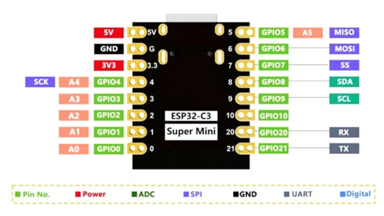
I’m new to electronics and looking to design a breakout board to connect my Qorvo DWM3000 to the ESP32 C3 mini although having some problems knowing what to do! I have currently put a basic diagram down but have no idea if this is correct and whether i need more components etc. Any help would be great as I’m sure this is a fairly easy task.
Functionality:
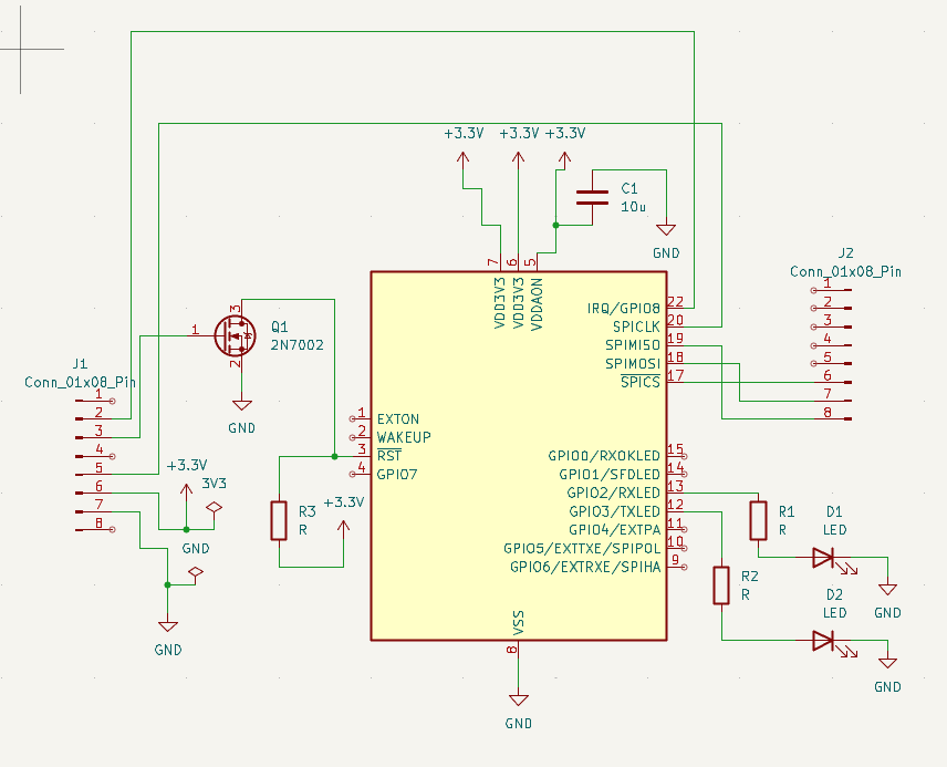
The reset pin shouldn’t be driven high, it should be driven by an open drain output. I don’t know if the ESP32-C3 supports an open drain output mode on the IO pins. If it doesn’t support that then you can create one by adding an n-channel MOSFET.
LEDs - Either these need to face the other way around or you need to connect them to power rather than ground.
Style (no effect on functionality, just makes for a more readable schematic):
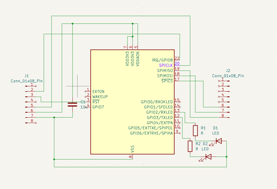
When drawing a schematic it’s normal to connect power and ground signals to a global net rather than drawing lines, it makes things look a lot neater and avoids too many crossing over lines.
So power from the connector goes to a global 3V3 net. And then next to the DWM3000 power pins you have a second global 3V3 connector going to the power pins and a capacitor.
The global GND net connects to the connector, the capacitor, the LEDs and the DWM3000.
Global power markers always point up. Global GND markers always point down.