The DWM1001 datasheet recommends that “the module is intended to be positioned vertically
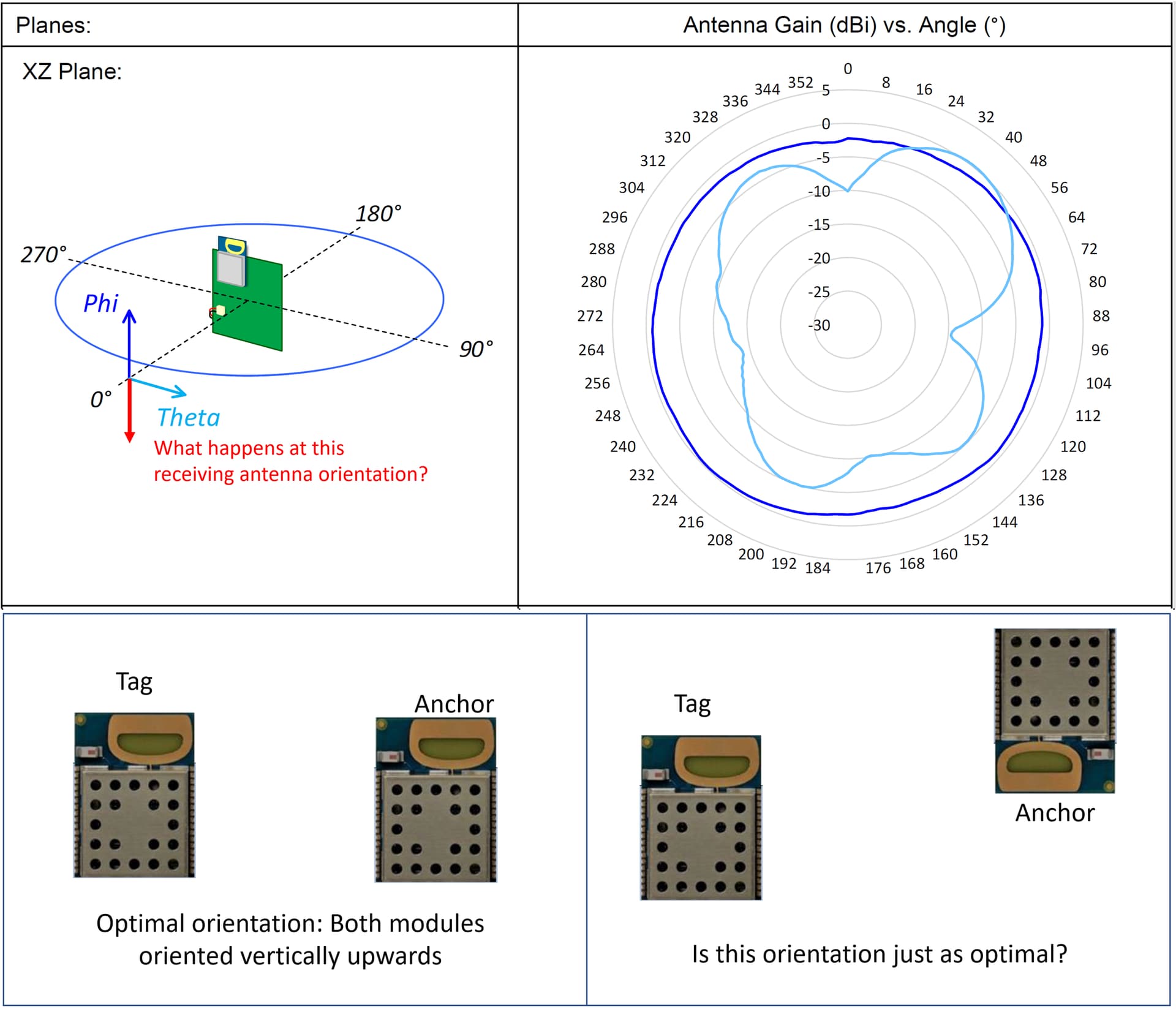
upright when used in an RTLS system”. This orientation provides the most omnidirectional radiation pattern between two modules as shown by the dark blue line in the attached image.
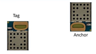
We are planning a system installation where anchors with DWM1001 modules are mounted from the ceiling with the antenna facing vertically downwards, while the tags have their antennas facing vertically upwards. Assuming the anchors and tags located on the same horizontal plane, would the antenna radiation pattern between them still be as optimal as when both antennas are oriented vertically upwards (see images below)?
Where the dashed line represent the direction you are interested. As you can see right below the DWM1001 module the (at 90deg) the signal significantly drops and it is bumpy - this is something you don’t want. While at 270deg it is not perfect but it is more like “constant”.
Thank you for your response. I agree that this is the best way to set up the system in this situation. Just for my understanding though, what would happen in the following scenario:
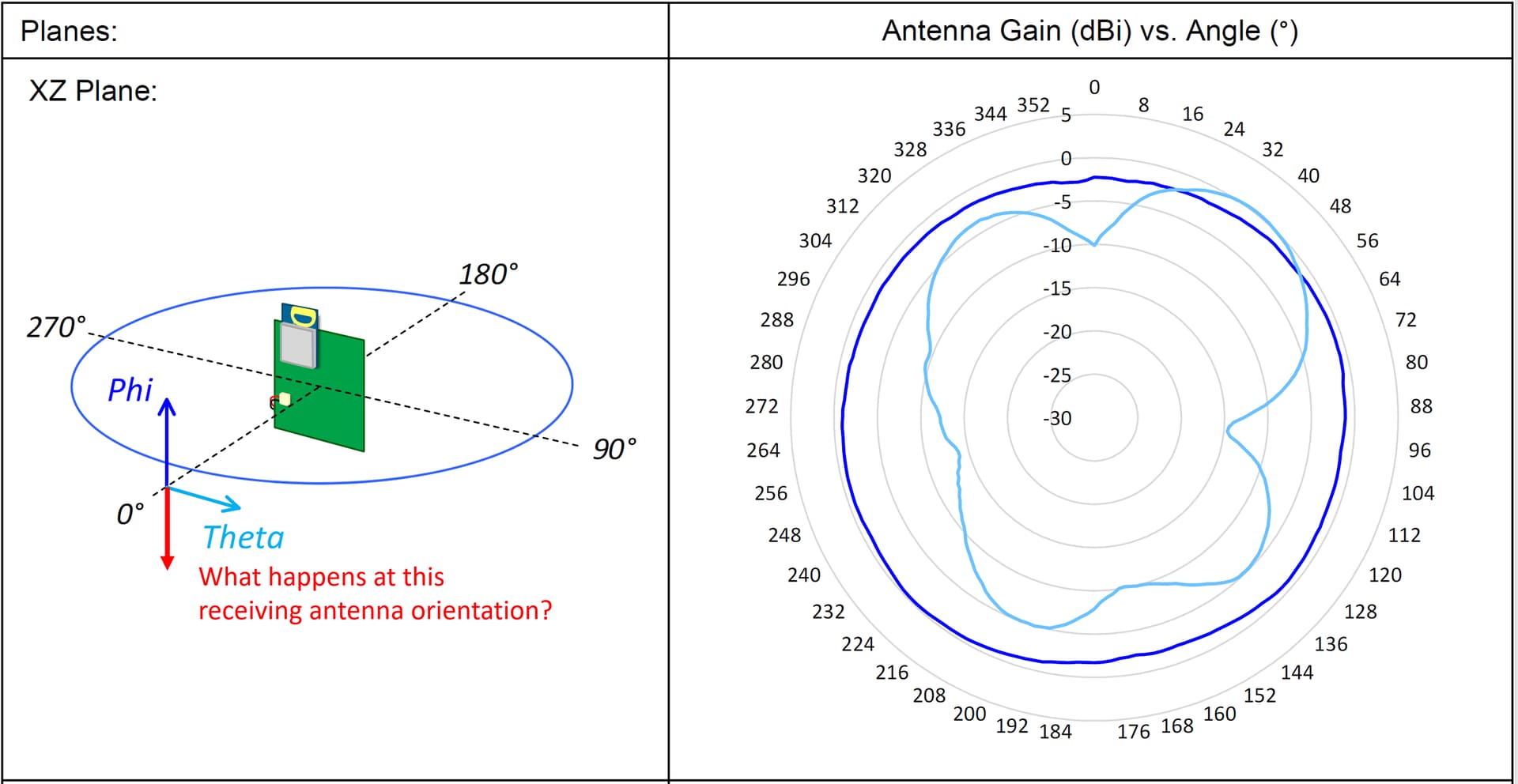
You perform the radiation pattern measurement in the x-z plane (as shown in the attached image below, note this is the x-y plane in the image you posted), but instead of having the receiving antenna oriented upwards in the phi direction, you rotate it by 180° to face downwards as shown by the red arrow. The transmitting antenna that is being measured is still pointed in the upward direction. Would you still measure the same dark blue pattern as when both antennas were oriented upwards?
Hi @kli
Im not sure if I follow your question. However when you change the orientation of the module you need to change the orientation of the plot accordingly.
One more note: The dark blue plot correspond with the dark blue circle around the devkit. I believe that the Phi and Theta arrows colors are swapped.
Yes. You will get the same antenna pattern. Or at least something very similar.
By rotating it 180 you’ll be maintaining the same antenna polarisation and rotation plane so it will give the same results.
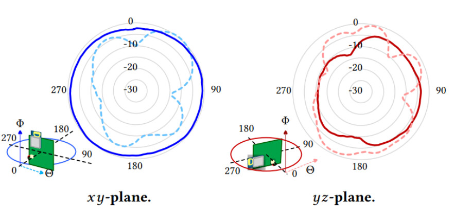
You indicated that you aim to keep all the antennas on the same horizontal plane. In practice this often ends up being very hard to achieve perfectly. Looking at the y/z results as long as the vertical angle between your tags and anchors is under around 20 degrees you shouldn’t see significant variations in gain.