DWM1000 SS TWR - tolerance drops almost twice after XTAL Trim

I am evaluating DWM1000 in SS and DS TWR examples. Observed that double-sided TWR gives narrower error distribution than single-sided due to elimination of clock speed difference from equation.

However I’ve noticed that SS TWR uses carrier integrator value to adjust the calculation of distance according to XTAL offset between communication parties . The same code of calling for dwt_readcarrierintegrator() is used int XTAL Trim example. So I’ve decided to give it a try and added few lines of code to trim the XTAL on the fly in SS TWR example (whenever it goes over 1.75 ppm).

// CONFIG :
	
 static dwt_config_t config = {
    2,               /* Channel number. */
    DWT_PRF_64M,     /* Pulse repetition frequency. */
    DWT_PLEN_128,    /* Preamble length. Used in TX only. */
    DWT_PAC8,        /* Preamble acquisition chunk size. Used in RX only. */
    9,               /* TX preamble code. Used in TX only. */
    9,               /* RX preamble code. Used in RX only. */
    0,               /* 0 to use standard SFD, 1 to use non-standard SFD. */
    DWT_BR_6M8,      /* Data rate. */
    DWT_PHRMODE_STD, /* PHY header mode STANDARD (127 MAC symbols). */
    (129 + 8 - 8)    /* SFD timeout (preamble length + 1 + SFD length - PAC size). Used in RX only. */
};


// RESPONSE PROCESSING :

/* Read carrier integrator value and calculate clock offset ratio. See NOTE 11 below. */
xtalOffset_ppm = dwt_readcarrierintegrator() * (FREQ_OFFSET_MULTIPLIER * HERTZ_TO_PPM_MULTIPLIER_CHAN_2);
clockOffsetRatio =  xtalOffset_ppm * 0.000001f;

/* Get timestamps embedded in response message. */
resp_msg_get_ts(&rx_buffer[RESP_MSG_POLL_RX_TS_IDX], &poll_rx_ts);
resp_msg_get_ts(&rx_buffer[RESP_MSG_RESP_TX_TS_IDX], &resp_tx_ts);

/* Compute time of flight and distance, using clock offset ratio to correct for differing local and remote clock rates */
rtd_init = resp_rx_ts - poll_tx_ts;
rtd_resp = resp_tx_ts - poll_rx_ts;

tof = ((rtd_init - rtd_resp * (1 - clockOffsetRatio)) / 2.0) * DWT_TIME_UNITS;
distance = tof * SPEED_OF_LIGHT;

// crystal trimming
if(fabs(xtalOffset_ppm) > TARGET_XTAL_OFFSET_VALUE_PPM_MAX)
{
	uCurrentTrim_val -= 0.65 * AVG_TRIM_PER_PPM * xtalOffset_ppm ;
	uCurrentTrim_val &= FS_XTALT_MASK;

	/* Configure new Crystal Offset value */
	dwt_setxtaltrim(uCurrentTrim_val);
	sprintf(msg_str, "XTALTRIM : %d\r\n", uCurrentTrim_val);
	Serial_WriteString(msg_str);
}

/* Display computed distance on UART. */
sprintf(msg_str, "DIST %3.2f m, XTAL %2.2f PPM, SQ #:%d\r\n", distance, xtalOffset_ppm, frame_seq_nb);
Serial_WriteString(msg_str);

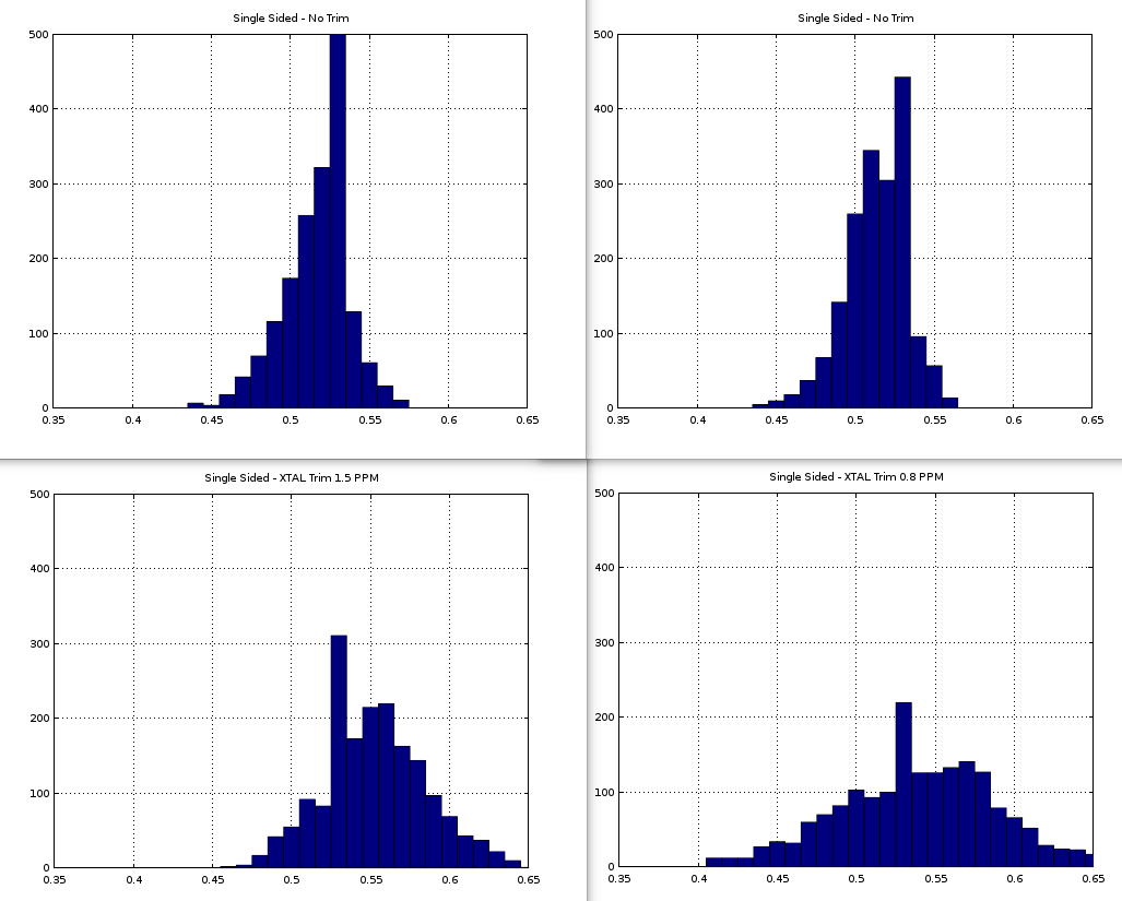
After few experiments I did some captures when crystal was trimmed at 0.20…080 ppm, and in another run where it settled at 1.2…1.5 ppm

To my big surprise, the error distribution became twice wider. The better the trim actually - the worse result I’ve got. These are histograms of measurement error distribution 1800 measurements each (distance is fixed and identical in all cases - around 0.55 meters). All measurements performed on the same setup.

Two charts at the top - typical SS TWR results I get without XTAL trimming. In this case the xtalOffset_ppm usually sits near -3 ppm.

Two charts at the bottom are measurement distributions with added crystal trim code block (lines 222 – 232). Technically trimming block executes only once or twice at startup, then the value settles in a range bellow TARGET_XTAL_OFFSET_VALUE_PPM_MAX = 1.75. I am just trying to say that while capturing data for two histograms at the bottom - there were no additional trimming performed in the process (no calls to dwt_setxtaltrim(), what can technically shift the timestamping).

Hi,

thanks for sharing the findings. They are very interesting and I would not expect that neither. I do not know why have you measured a such values.

In general on DWM1001 and PANS the modules are trimmered in the factory and we do not experience a such standard deviation as you have measured. It would look rather like the top figures.

Perhaps try to add some delays after the trim to see if it would have any effect.

Cheers,
TDK

My workshop room is not exactly an RF-lab, but it replicates typical environmental conditions in which the device will be used - my apartment :slight_smile: . So I am not measuring the parameters being up to the spec in DataSheet, but rather relative performance differences under various configuration settings.

On both bottom charts the trim code section was already executed a minute earlier and the data capture done when the trim value settled. (I am running at a rate approx 100 measurements per second). The code itself has this gate condition

if(fabs(xtalOffset_ppm) > TARGET_XTAL_OFFSET_VALUE_PPM_MAX) { ... }

so once it executes - the XTAL trim gets bellow this threshold and the trimming code never executes again (until you power-cycle the device, or there will be some big change in environmental conditions - like huge jump in surrounding temperature).

Two bottom charts are 1800 samples each where in one case the XTAL trim settled at 1.2 …1.5 PM and in another at 0.3 … 0.8 PPM. the measured xtalOffset_ppm has the deviation of approx 0.5 ppm (I assume due to phase noise, etc). Without trimming xtalOffset_ppm value jumps around 3.5 ppm. So the conclusion is that either an offset trim of 4 ppm just gives better perfromance, or the actual xtalOffset_ppm code has bugs in the driver (e.g. wrong values for FREQ_OFFSET_MULTIPLIER and HERTZ_TO_PPM_MULTIPLIER_CHAN_2m, what I did double-check with my config 5 times).

I am planning to write some code, which will search for best trim value automatically by monitoring STD on every 200 samples or so. Instead of trying to get xtalOffset_ppm close to 0 - it seems that the actual “perfect trim” value may be different from 0. Just because of driver error, or the PPM estimation approach used.

Just for the sake of experiment - implemented a simple algorithm that deliberately offsets the XTAL trim through the range of 20 positions (+/-10 from factory setting), searching for the minimum of standard deviation on 2000 measurements. The best result achieved at -24 ppm.

I assume these results are outcome of surrounding RF conditions, my thing is assembled using home-made PCBs and with STM32 dev board mounted into 3D-printed enclosure. Maybe reflections from nearby metal components make more accurately trimmed DWM1000 perform worse. I do expect to see some more sanity in the data produced by this experiment after redesigning the whole thing into 4-layer board. But this is kind of a hint to everyone else - try swiping through the hole range of available XTAL offsets and observe what happens with standard deviation of your measurement on each setting. I don’t think that the best STD at higher trim-offset will persist if I change the setup/environment. And having the offset at -24 PPM puts me at risk of increased errors rate at larger distances. I did not notice any difference in current error rate, getting like 1…2 failures per 1000 measurements. But I assume at a such short distance (0.55 m) the error rate is more affected by surrounding RF noise from other sources (WiFi, Cell grid, etc)

Just sharing some measurements at alternative setup.
At 7 meters distance got the best results at +8 PPM XTAL trim (factory setting: 17, new best setting: 20). RF path obstacles: drywall with metal studs and couple bicycles. Also attaching the chart of how the standard deviation depends on XTAL trim setting (each point at that chart is an STD by 2000 measurement points, two sweeps at a a rate of approx 250 measurements per second).

1 Like

Hi Oleksandr,

thanks for sharing the interesting results!
The last two histograms: does the left one have incorrect description? It should be with factory trim 17 I guess?

If I understood correctly then at the distance 0.55 m the best trim was at -24ppm while at 7m it was 20ppm? Have you done it using the same hardware in similar temperature condition?

Can you please do a test at 7m with perfect LOS condition? And then place some obstacles in between and measure again? The crystal by itself should be fairly stable for the same temperature condition. What might happen is due to the reflection the carrier integrator will detect the signal with changed phase resulting in higher variation in the distance measurement.

I think using DS-TWR would confirm the above assumption.

Thanks,
Cheers, TDK

The left histogram on the left picture is correctly named. Both histograms are just two runs done with the same setup and configuration, the second was perfromed 30 min later after the first.The first histogram correspond to the green line on the right chart at offset 20. The second histogram correspond to the blue line in the right chart at offset 20.
Where 20 is a trim value that was passed to setxtaltrim() function before the data for the histogram was captured. That resulted into average +8 PPM offset calculated from getcarrierintegratorvalue() when histogram data was collected for the offset 20. The actual STD is almost the same on both hitograms (both drop in range of 10 cm). The small difference might be explained by the environmental conditions change between two measurements (e.g. AC turning ON and OFF while measurements were done).

What I am trying to figure out here - is that if I use getcarrierintegratorvalue() and trim the crystal until the computed PPM offset will be close to 0 - I am getting the worst deviation across the whole range of possible XTAL trim setting. See the very first picture I’ve attached in my first post - two bottom histograms. The better the trim - the worse standard deviation of distance measurement.At close 0 PPM (bottom right) the range of measured values is over 20 cm. And this applies for both - short (55 cm) and long (7m) distance measurements.

So I’ve kinda implemented the XTAL-calibration procedure that deliberately sets the offset value, disregarding how big this actual PPM offset is, but targeted to achieve best the best standard deviation of distance measurement. Swiping through every possible setting of XTAL trim and getting 2000 measurements on each takes about two minutes, so can be executed once in while and the results stored in flash memory of the host controller to apply at DW1000 power-up (or save XTAL trim to OTP memory).

Hi Oleksandr,

It could be the signal-correlated quantization noise.
In the PDoA application we use about 2ppm clock offset between the Node and Tag - to measure a very small values of phase differences of arrival this small clock offset is enough to get rid of this noise.
For the phase measurements we are using accumulator as you do for clockOffsetRatio compensation.

2 Likes