DWM1000 Ranging not working but data transmission works with STM32L151 and STM32F103

We as a company trying to do a solution for tracking using DWM1000 modules. We have already made a POC (Proof of Concept) model for the testing.

All Tags and Anchors was based on STM32 MCUs and the initial firmware developers have used the dwm1000 driver provided by the manufacturers themselves.

That firmware worked on the POC hardware and gave approximately correct results.
The firmware that was written by the developer was kind of convoluted and was really hard to understand what’s going on. Therefore another in-house developer has ported the Arduino-dw1000 library (GitHub - thotro/arduino-dw1000: A library that offers functionality to use Decawave's DW1000 chips/modules with Arduino.) to STM32. It also worked on the POC hardware.

But due to a technical difficulty we had with that library we had to change the library. Because one of the features that we were interested in was no supported by that library. Therefore we fall back to the dwm1000 driver provided by the manufacturers. But this time the firmware developer (myself) re-wrote abstraction layer for that driver from scratch and made it work on the POC hardware.

Since the POC is working and giving the correct results we moved forward to the next stage of the product development which is the prototype phase.

Due to some additional requirements we had to change the POC schematic into a new one and re-wrote the DW1000 driver’s abstraction layer in C++ for modularity.

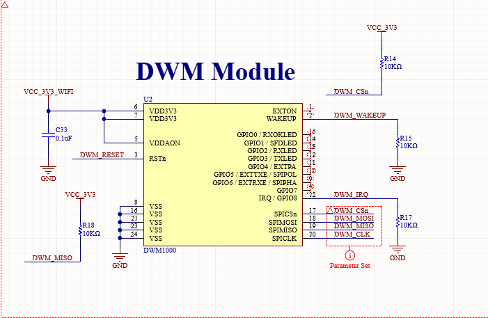
New DWM1000 schematic block

After we manufacture the boards and assemble it we did the initial test with the dw1000 driver which has the C++ abstraction layer. Sadly we couldn’t even get the Device ID (0xDECA3001) from the register.
The data coming into the STM32 through the MISO line was really unstable. Therefore the hardware team had to remove the PULLPUP resistor on the MISO line to make it stable. By stable I mean proper Square wave signal.
Even after that MISO line PULLUP resistor removal the DeviceID was not correct.
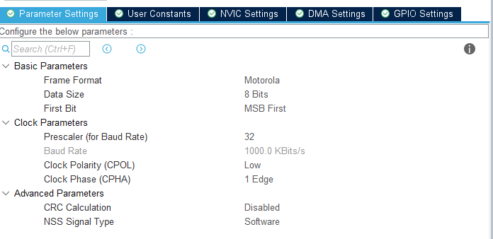
Eventhough the DeviceID registry is not a registry that needed SPI CLOCK to be less than 3MHz. we had to reduce the SPI CLOCK speed to 1.4MHz to make the STM32 talk to DWM1000.
That was the case in,
• DW1000 driver with C++ abstraction layer
• DW1000 driver with pure C abstraction layer
• DW1000 driver with the given examples
• Arduino-DW1000 library

After the SPI clock was reduced to 1.4MHz. the STM32 was able to talk to DWM1000 module and was able to get the DeviceID successfully.

Then we tried to do the ranging between 2 of the PCBs. One PCBs running Two-Way-Ranging-Initiator and other running the Two-Way-Ranging-Responder.

This codebase was a C++ abstraction of the DW1000 driver. But the Ranging was not occurring. Therefore we tried,
• DW1000 driver with Pure C
• DW1000 two-way-ranging example
• Arduino-DW1000 library

All above attempts were failed on getting ranging.

Therefore we tried another Arduino based library which is a fork from the previously mentioned Arduino-DW1000 library (GitHub - F-Army/arduino-dw1000-ng: Arduino driver and library to use Decawave's DW1000 IC and relative modules.)
For our surprise it did worked without any issues. Therefore the firmware developer (myself) ported that library to STM32 HAL and indeed it worked. Gave the correct results.

Once we were sure the DWM1000 modules on our PCBs were working correctly. We assembled the rest of the product and tried testing again.
For our surprise the ranging didn’t work at all. It’s the same firmware we tested before we assemble the PCBs inside the enclosures.

Since we know that the firmware worked before assembly we tried again and again few times.

The ranging happens like once every 10 times for few seconds and then nothing.

No interrupts are occurring, Ranging requests are timing out.

Today also we tested. For few minutes the ranges were coming. But they were wrong. The ranges gave from the responder side was -30000.000 meters. Which is clearly wrong. But when we re-ran the debugger then after that nothing came. Not even the wrong distances.

I did few things,

• Compiled and flashed the simple_rx and simple_tx example codes
STM32 devkits can run the code without any issues and the devkits receives the packets that are being sent by the “sender”.
• Increased the DWT_TIME_UUS and other time based variables in twr_responder and twr_initiator example codes

Additional Information,

MCU : STM32F4
CPU Clock : 64MHz
SPI Clock : MIN: 1.4MHz, MAX: 16MHz

Channels tried : 2 and 5
PRF tried : 16MHz and 64MHz
Data rates tried : 110K, 850K

Nothing seems to make the ranging work. But in all above test cases the “Simple_RX” and “Simple_TX” example works without any issues. But the ranging examples doesn’t

@AndyA Can you help me on this

Any chance you can post more of the schematic and/or the board layout?

Your firmware works on other hardware. Changing the SPI speed has an impact on how well things work. A pull up resistor was having a significant impact on signal quality.

All of these things point to a hardware issue. It could also be a misconfiguration of the SPI interface in the processor (e.g. the wrong SPI mode) but that would impact other hardware too unless that part of the code changed when you moved to new hardware.

Anchor Board.pdf (810.9 KB)

Here is the Schematic and board layout file.


this is the configuration for SPI Peripheral.

My Main problem is that,
the simple_rx and simple_tx examples work without any issues. but when it comes to twr_initiator and twr_responder then that examples are not working.

The ranging examples will be pulling more power and transferring more data over SPI and so be more prone to hardware issues. Do the timings in the ranging examples allow for the lower SPI bus speed you are using?

You said that with an SPI speed of 3MHz it didn’t work but at 1.4 MHz it did. With traces that short you should be able to run that SPI bus at 20 MHz without any issues.

There is no clear reason why a pullup on MISO should have been causing any issues at all. The layout isn’t perfect but it doesn’t look bad enough to cause this sort of issue. On the schematic side I would have put a far larger capacitor in parallel with C17 after FB1 but C7 should save you there.

Have you checked for high frequency dips on the 3.3V rail while the system is running just to be sure it’s not showing any issues?

How are you driving the DWM_RESET line? That pin should be set as an open drain output or an input.

3.3V on oscilloscope

above video shows both twr_initiator’s and twr_responder’s voltage levels during the ranging.
both voltage levels seems stable and no dips. But give us your thoughts.

DWM_RESET is configured to be a INPUT for the STM32 using the STM32CubeIDE.

Do you have a tried and verified code in C or C++ for STM32 so i can try that in our product too? just to eliminate the possibility of that this is a firmware issue. (Yes we tested the firmware before the assembly of the system and it worked. but just to be sure we would like to try a code that tested and verified to be working)

just to rephrase what we tried,

  1. DWM1000 Arduino Driver ported to STM32 (GitHub - thotro/arduino-dw1000: A library that offers functionality to use Decawave's DW1000 chips/modules with Arduino.) => Worked On POC hardware not on Prototype hardware. Didn’t work even once
  2. DW1000 driver provided by Qorvo. which is already a STM32 based driver => Worked on POC hardware not on Prototype hardware. Didn’t even work once
  3. DWM1000-Ng arduino library ported by firmware developer (myself) to STM32 (GitHub - F-Army/arduino-dw1000-ng: Arduino driver and library to use Decawave's DW1000 IC and relative modules.). => Worked before assembly of the prototype hardware, Worked once or twice after assembly. but not working now.

We would like to ask for a ranging example code/driver that you tested on STM32 if possible.

Personally I would have put the scope in AC coupled mode, that often works better for finding noise on a power line since you can turn the sensitivity up. And also increase the time resolution, you are looking for very short noise spikes. You need to be measuring on the DWM1000 input pin if you weren’t.
Having said that as long as you had the probes in x10 mode I would have expected to see something with those settings if the power was bad enough to matter.

I don’t have STM based code, we use our own driver which is very tightly linked in to a lot of our performance optimisations and are using an LPC processor.

But you have known working code on other hardware. So either some mistake was made porting that code to the new hardware or the new hardware is faulty.

@AndyA
Since you mentioned there is a possibility of software being faulty too.
So what i did was to try the DW1000 driver examples (ss_twr_init and ss_twr_resp) again on the prototype hardware. This time instead of adding breakpoints on the ss_twr_init (where the Distances are being calculated) i set some breakpoints on the ss_twr_resp.

This is what i observed,

  1. i get the correct frame from the ‘ss_twr_init’

if (memcmp(rx_buffer, rx_poll_msg, ALL_MSG_COMMON_LEN) == 0)

above line is true. that means the frame is correct.

  1. dwt_starttx() also getting success

ret = dwt_starttx(DWT_START_TX_DELAYED);

which means the ss_twr_init side sending the correct frame and the ss_twr_resp side is receiving that frame like expected and sending the timestamp back.

so once i saw that i knew 3/4th of the communication works.

then i started debugging the ss_twr_init side.

since the correct flow is happening on the ss_twr_resp side that means,

dwt_starttx(DWT_START_TX_IMMEDIATE | DWT_RESPONSE_EXPECTED);

line works correctly. but,

while (!((status_reg = dwt_read32bitreg(SYS_STATUS_ID))&(SYS_STATUS_RXFCG|SYS_STATUS_ALL_RX_TO | SYS_STATUS_ALL_RX_ERR))) { };
frame_seq_nb++;
if (status_reg & SYS_STATUS_RXFCG)

but the above last line always returns false.

So that means the response from the other side is not quick enough right?

#define UUS_TO_DWT_TIME 65536
#define POLL_TX_TO_RESP_RX_DLY_UUS 140
#define RESP_RX_TIMEOUT_UUS 210

just for information these are the values that we are using on the ss_twr_init side.

Do you have an idea whether these values are the reason for the ranging to fail on he ss_twr_init side.

As I mentioned previously if you have turned the SPI bus speed down you may need to increase the delay times to allow for the communications to the chip being slower. You can either work this out or the simple test would be to increase the POLL_TX_TO_RESP_RX_DLY_UUS and RESP_RX_TIMEOUT_UUS values by say 50 us to give things more time.

But you shouldn’t need to turn the SPI speed down to start with. Turning the speed down and increasing the times may work but it would only ever be a workaround that’s masking a more fundamental problem. And the trouble with leaving fundamental problems unsolved is that they tend to come back and bite you.

1 Like

I think fundamentally you have issues on hw / spi block.

In DW1000 chip, it has a bit which is slightly changing the behavior of the MISO. what it does is basically holding the MISO a bit longer than by default.
It would limit the max SPI speed to 18 MHz.

It was discussed multiple times here. What you need to do is just write something default to the chip as the first ever command after startup.
Search UM and this forum.

Wrt TWR:
Decawave created a tons of documentation, in particular APS022 which shall help understand how TWR works.
https://www.decawave.com/application-notes/

Also, you understand that dw1000 has a limitation of 3.5MHz before init and 20 on high speed? Check how you are switching the speed in your code.

Also, you understand that dw1000 has a limitation of 3.5MHz before init and 20 on high speed? Check how you are switching the speed in your code.

regarding this. yes. I switched the SPI bus speed to 1.4MHz before initialization and i make the SPI bus speed 18MHz just before i start the ranging process.

I think fundamentally you have issues on hw / spi block.
In DW1000 chip, it has a bit which is slightly changing the behavior of the MISO. what it does is basically holding the MISO a bit longer than by default.
It would limit the max SPI speed to 18 MHz.
It was discussed multiple times here. What you need to do is just write something default to the chip as the first ever command after startup.
Search UM and this forum.
Wrt TWR:
Decawave created a tons of documentation, in particular APS022 which shall help understand how TWR works.
Application Notes - Qorvo

regarding this response. i will check this and get back to you.

I also ported dw1000 stm32 library on rp2040 but after software reset i am just getting 0xfffff from register value. Help me to resolve that. If you can share your. Ode than I can try your code on stm32.

0xffff is the default value you will get from an SPI bus if the device doesn’t respond.

I am debugging that problem. It only occurs when I write in the PMSC (Power Management System Control) register. I don’t know why it happens and why it exhibits this strange behavior. If anyone has dealt with the same issue, please share the solution.