Hi,
Using different clock speed from 10kHz to 4MHz I get some problem with the output the spi give me. (miso). I created a loop that repeats itself every 0,5s which does only read the TX_FCTRL REG and here is a sample of the result I get.
Transmit frame control 0x c c0 15 0 0
Transmit frame control 0x c c0 15 0 0
Transmit frame control 0x c c0 15 0 0
Transmit frame control 0x ff ff ff ff ff
Transmit frame control 0x ff ff ff ff ff
Transmit frame control 0x c c0 15 0 0
Transmit frame control 0x c c0 15 0 0
Transmit frame control 0x c c0 15 0 0
Transmit frame control 0x ff ff ff ff ff
Transmit frame control 0x ff ff ff ff ff
Transmit frame control 0x c c0 15 0 0
Transmit frame control 0x c c0 15 0 0
Transmit frame control 0x c c0 15 0 0
Transmit frame control 0x c c0 15 0 0
Transmit frame control 0x ff ff ff ff ff
Transmit frame control 0x ff ff ff ff ff
Transmit frame control 0x c c0 15 0 0
Transmit frame control 0x c c0 15 0 0
Transmit frame control 0x ff ff ff ff ff
Transmit frame control 0x ff ff ff ff ff
Transmit frame control 0x c c0 15 0 0
Transmit frame control 0x c c0 15 0 0
Transmit frame control 0x ff ff ff ff ff
Transmit frame control 0x c c0 15 0 0
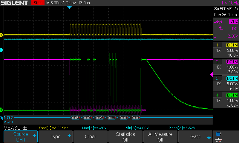
What you see is not a problem with my program in showing the data. I confirmed the data here with my oscilloscope and it’s the DWM that is returning all those one to me.Here I am only reading the FCTRL REG but if I read the SYS_STATUS, wait 500ms, read the FCTRL and wait again in a loop, I get the problem on both reading. Finally if I only read the SYS_STATUS then I get no problem ever.
Doing my research, I found out the CLKPLL_LL bit in the STATUS register was at one. What I did is set the bit PLLLDT in the EXT_SYNC register and then I clear the CLKPLL_LL bit and it doesn’t come back until I reset the micro.
But this didn’t fix my problem. Trying with another DWM didn’t do it too.
I really need help so thank in advance even if you just tell me about somewhere I can get more info.
The SPI on the device works so it’s either your firmware or something to do with the hardware. Given the intermittent nature my guess would be a hardware issue.
You are using the DW1000 chip directly or the DWM1000 module? Your post is tagged with both, the title has DW1000 but then your question says DWM.
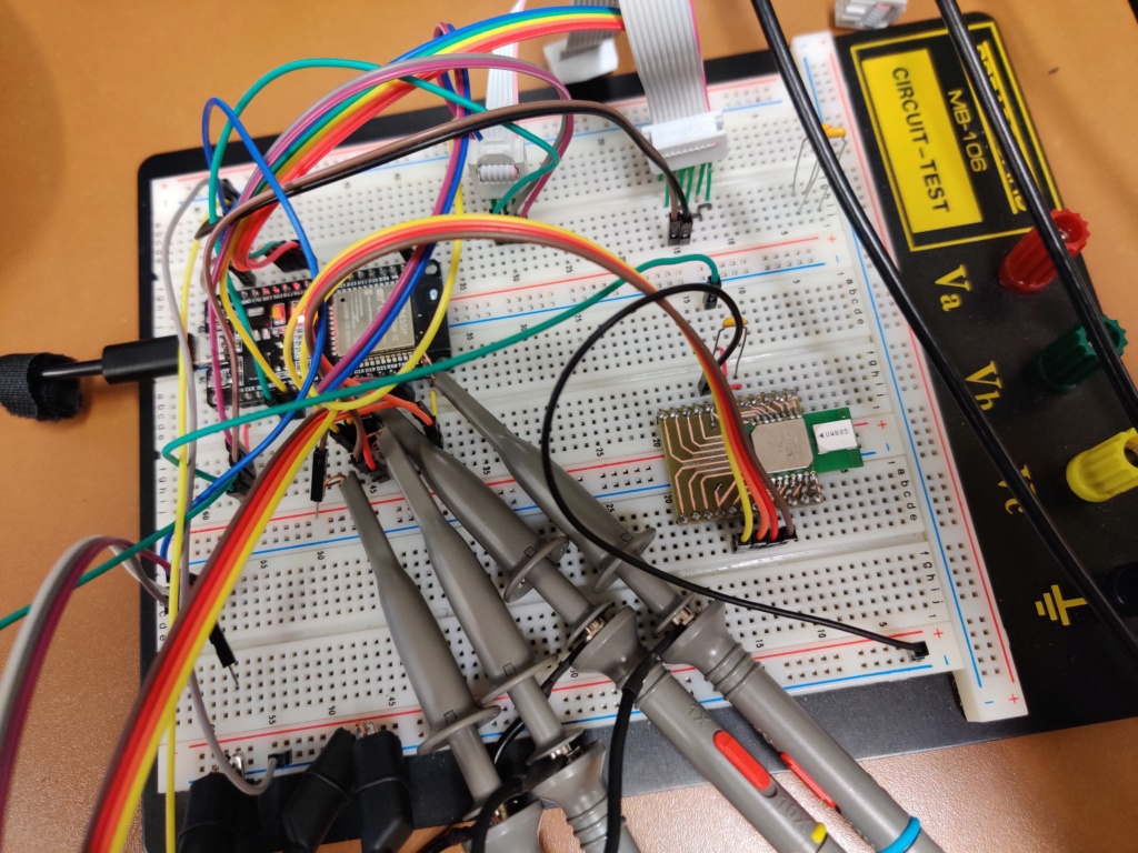
What does the signal quality of the SPI signals look like at the DW[M]1000 inputs?
Is the power supply to the DW stable and low noise?
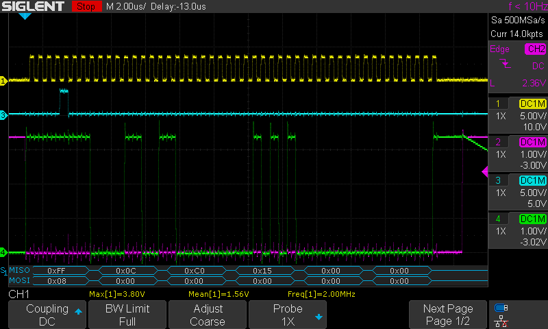
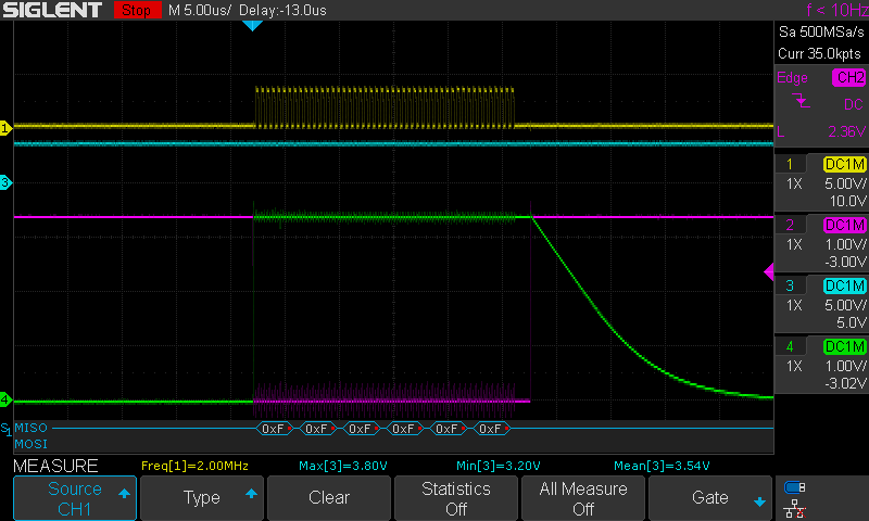
As we can see, the mean value almost never change and I saw that the minimum never change too, always 3V when I have data and 3.2V when it’s all one.
Since it may be a power issue, I tried to power only the dwm1000 with my workbench power supply which is more reliable. When I checked the data of the TX_FCTRL register like in my previous image, it didn’t change anything (same bug).
Lastly, as I said before, when reading the data of the SYS_STATUS register, I don’t have any issue but here with the workbench supply I had transmission that where all one.
So maybe you are right and the problem comes from the power supply but then what I think to be a better power supply is performing worst.
Put your scope probes into x10 mode. NEVER use x1 unless you have a very good reason.
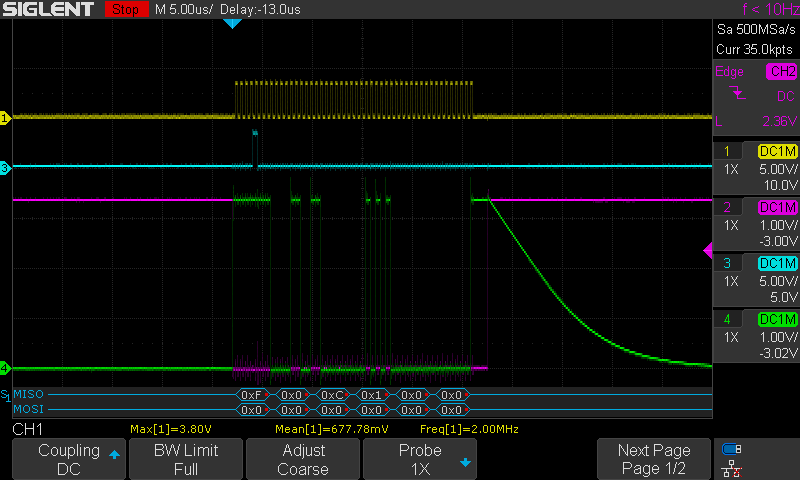
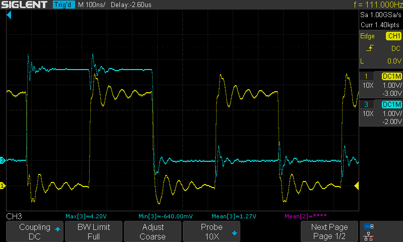
Can you measure the clock and the MOSI signals at the DWM1000 with the time base decreased so that you can only see a couple of cycles. Ideally with a better probe ground connection also taken from the module.
You look to have a lot of noise on the data lines but I can’t tell if that’s the way you have the probes hooked up or genuine noise on the signals.
Looking at that it’s not great, but it should work.
My concern was that you were getting noise on the data line caused by cross talk from the clock line. While there is certainly some noise there it looks to be small enough that it shouldn’t cause the problems you’re seeing.
In the future when using ribbon cables like that try to put a ground either side of the clock and data signals, it’s not always possible for prototypes but it does help prevent this issue.
It looks like you are connecting all 3 power pins.
Are the grounds all connected together on the back of your pcb or are you counting on the module to connect them? f possible tie them all together as much as possible. You may even be able to do that with short wires under your module.
Given the cable lengths on power and ground and the round about route your ground is connected extra capacitance from VCC to ground isn’t going to hurt but I’d be surprised if that was the issue.
I hate and hate so much my problem but you help me accidently finding it. Theres is no problem with my circuit until I tries to measure it. The problem was the position of my probe. I seriously don’t understand it. Okay probe do interfere with the circuit it measure even if it’s small but I mean. I was near the esp32 not the dwm and the data of the 0 and 1 or clear opposite so how could it interfere so much on a random basis like that ? If you know rescource I could search on that topic I would like to have it.
Thank you for your help
I’m only starting my project with the dwm so maybe to a next time.
Dythe
A scope probe adds around 150pF of capacitance plus if you’ve added extra wires to get to the signals you’re going to get a reflection from that. When in x10 mode the effect of the probe is more like 15pF which is why you should always use them in that mode.
If the data coming out of the module was a solid 1 then that would indicate that the issue was with the data going into the module, either the edges or timing of the signals at the DWM1000 inputs, that’s why I asked you to measure at that point rather than at the processor.
This sort of signal integrity issue can be a nightmare to track down. On the plus side they tend to go away or at least get a lot better once you have a real PCB rather than a breadboard.