DWM1000 crystal trimming resolution worse than expected

Hello everybody

I’m having an issue with the crystal trimming feature on the DWM1000 modules I have here.

From the DWM1000 module datasheet, Table 9, I understand that the trimming step size should be around 1.6ppm/step (i.e. +/-25ppm “on-board crystal trimming range” and XTALT range 0…31)
The comment in the API source code for dwt_setxtaltrim() also claims approx 1.5ppm/step. Though the latter may not apply to the DWM1000 as the API does not seem to specifically target this module.

However, when testing, the smallest frequency offset step change I get is approx 3.2 - 3.5 ppm/step. I’m not using the API, but I’m reading back the XTALT value and I verified I’m indeed changing at 1-step increments.
I’m measuring the frequency offset with both RXTOFS and DRX_CAR_INT and they agree.
The step size is the same on two modules I’ve tested with.

Can anyone confirm this behaviour is correct for the DWM1000 (any why) or has any hints of what I might be doing wrong?

Thanks, Felix

Hello, the frequency oscillations are usually due to the temperature, if you can repeat your tests under a controlled temperature of 25 ° C, you may approach the data sheet.
TCXO normally minimize these oscillations.

best regards

By co-incidence I was testing this the other day - testing one of our prototypes (DW1000 module) against a production unit (TCXO). The temperature was steady room temperature.
Testing on a spectrum analyser using CW mode and reading RXTOFS.
Trim value - error (against TCXO module as datum)
x0C - 16ppm
x0E - 8ppm
x10 - 1ppm
x12 - -6ppm
x14 - -12.5ppm
x16 - -18ppm

This ties in closely with your findings, i.e. 3-4ppm per step.

Hello @FAlthaus, welcome to the Decawave forum

The trimming step size should indeed be ~1.5ppm on the DWM1000, though it is not 100% linear (but it is linear enough for most use-cases). For other crystal load capacitor values (e.g on different modules or chip-down designs) the range and step side could be different. Note that RXTOFS and DRX_CAR_INT are dependent on the clock of both the transmitter and the receiver, and I think it might also be impacted by the antenna delays.

The FS_XTALT register trims the internal reference frequency. I suggest looking into the continuous waveform transit function (dwt_configcwmode) and using a frequency counter or spectrum analyzer to accurately measure the reference frequency. Could you share the values for RXTOFS and DRX_CAR_INT and FS_XTALT you found?

As @Fdiaz noted, the reference frequency will also change due to change in temperature. However, the step size when changing FS_XTALT should stay more or less constant. It is advisable to let the module achieve “temperature equilibrium” when measuring the center frequency. This is a bit tricky in real-world scenarios since the DW1000 will heat up when active (transmitting or receiving) and cool down when inactive, using the continuous wave mode makes this a bit more easy. Note that a temperature difference between both modules could also explain a frequency offset.

When you need a more accurate clock, you could look into using an external TCXO. See section 8.1 of the DW1000 user manual and section 5.2 and 8.1 of the DW1000 datasheet.

Thank you all for your replies.

I’ve done some more measurements, and I’ve also implemented an offset measurements based on RX timestamps while precisely setting the period between two TX packets via delayed transmission (as described here: Method #2 for tuning? - #3 by mciholas). This should serve as a somewhat independent measurement (and I don’t have a frequency counter or a spectrum analyzer available at the moment)

Here the raw RXTOFS and DRX_CAR_INT values as read from the chip and after performing sign-extension, each step is a +1 or -1 change in XTALT:
ch1_clk_offsets

Here the calculated relative offsets between TX and RX (signs may not be correct as I just wanted to overlay the data to compare):
ch1_clk_offset_all

Measurements are for Channel 3, but they look similar on other channels. The TX was transmittig packets at a fixed period, while the XTALT on the RX was changed at +/-1 increment/step. The results look the same if I keep the RX tuning fix and change it on the TX.
All measurements have been taken at room temperature (fairly stable) and after letting the modules reaching something close to thermal equilibrium.

All three values agree quite well, so it looks to me the tuning resolution is in fact in the order of 3-3.5ppm/step, no matter what the datasheet states.

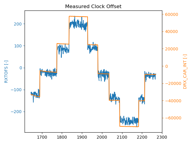
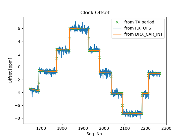
Nice data, thanks for doing that and posting the results in an informative way.

It depends on the crystal circuit.

The way the trim works is selecting additional capacitance on the XTAL pins. The added capacitance is a fixed value based on the manufacture of the DW1000 chip, described as being 7.75 pF maximum value in the datasheet, which is 0.25 pF per step over 31 steps. The selectable capacitors are thus 4 pF, 2 pF, 1 pF, 0.5 pF, and 0.25 pF, each enabled by one of the bits in XTALT.

38.4 MHz crystals can be had with loading capacitance parameters from 4 pF to 22 pF. If your crystal has a 4 pF loading value, then a 7.75 pF adjustment is much larger shift in the crystal’s frequency than if the crystal has a 22 pF loading value.

The adjustment step depends on the crystal chosen, which affects the loading caps put on the PCB, and thus affects the adjustment range of XTALT.

Section 5.14 of the DW1000 datasheet covers this topic and says:

“The type of crystal used and the value of the loading capacitors will affect the crystal trim step size and the total trimming range.”

They give formulas to compute what range and step you will get for a particular setup.

For those designing their own boards, what value is ideal for the crystal load capacitance?

If you want fine adjustment with XTALT, then selecting a crystal with high loading, say 20 pF, results in the finest adjustment, but more limited range. You will want to get a 10 ppm crystal to be sure you are “in range”. A downside to the high loading is increased energy usage since the signal is being loaded by 40 pF capacitors on each crystal pin. This is likely around 5 mW power usage for that loading.

If you want lowest power and don’t care about fine adjustment via XTALT, then select a crystal with low loading. Now it can also be lower tolerance since you have a bigger adjustment range, so perhaps 30 ppm works. The power savings are something as an 8 pF load crystal uses about 2 mW of power.

You may think the 3 mW of power savings isn’t much given the DW1000 power usage during receive and transmit is 100s of mW. But, if you duty cycle the DW1000 between SLEEP or DEEPSLEEP and TX/RX modes (as any good tag design will do to save battery), there’s a 2-4 ms period before the DW1000 can operate where it is starting the crystal oscillator (INIT phase). Those extra 3 mW of power exists during that time. So you have, say, 3 ms of an extra 3 mW, 9 uJ extra due to high crystal load. The energy you spend sending a blink, say 100 us long and 200 mW, is 20 uJ. Now it doesn’t seem so small in comparison, about half the transmit energy was lost in crystal loading in a tag that sleeps between blinks.

The higher load capacitors also improve the crystal robustness against noise injection and are somewhat more stable. It is harder to push the signal around if it operates under more load, and small changes in capacitance (which can occur with temperature changes) don’t upset the frequency as much.

Mike Ciholas, President, Ciholas, Inc
3700 Bell Road, Newburgh, IN 47630 USA
mikec@ciholas.com
+1 812 962 9408