Hi all, I am Utku Serin from Izmir,Turkey.
I am using the DW1000 library by Thomas Trojer in the Arduino IDE.
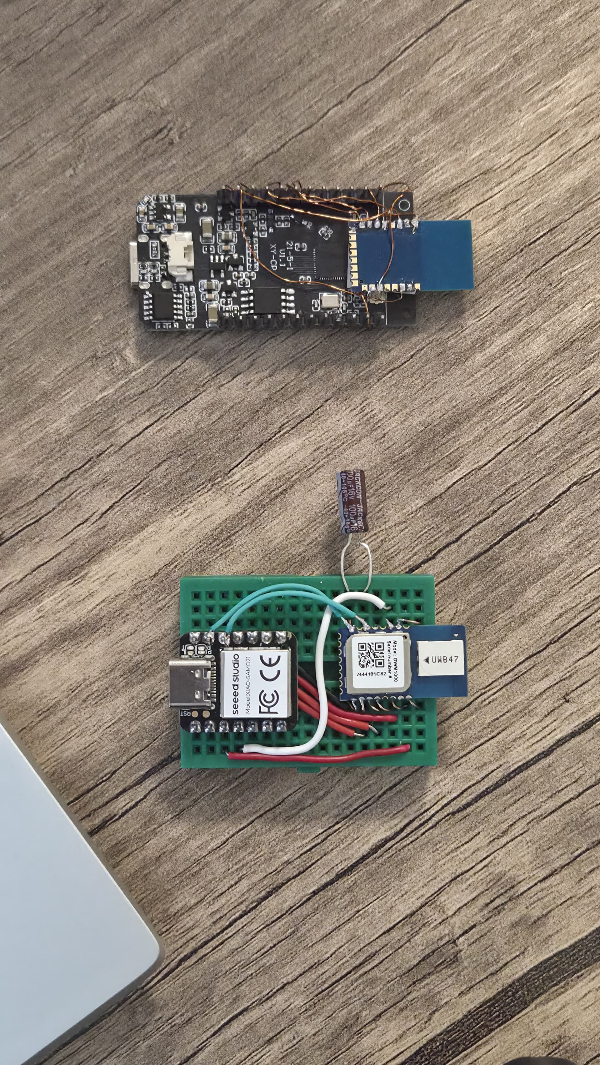
There is a LILYGO t-display ESP32 module as an anchor with one of the DWM1000, and there is a seeeduino XIAO as a tag with other DWM1000 module. I have done the necessary SPI connections and uploaded the example codes that come with the library(“DW1000Ranging_ANCHOR.ino”, “DW1000Ranging_TAG.ino”) to the microcontrollers separately. I can read IDs correctly. As you can see from the serial print messages range is wrong, I can fix it by using delay adjustment, but also the RX power is too low. No matter the distance between the anchor and the tag, RX power does not change. It is -84dBm at 2 cm. I think this is the main problem.
*device address: 82:17:5B:D5:A9:9A:E2:9C*
*### ANCHOR ###*
*blink; 1 device added ! ->  short:D325*
*from: D325         Range: -95.30 m        RX power: -84.33 dBm*
*from: D325         Range: -106.99 m       RX power: -84.31 dBm*
*from: D325         Range: -27.71 m        RX power: -84.14 dBm*
*from: D325         Range: 29.40 m         RX power: -84.57 dBm*
*from: D325         Range: 83.07 m         RX power: -84.47 dBm*
*from: D325         Range: -1.40 m         RX power: -84.27 dBm*
*from: D325         Range: 39.61 m         RX power: -84.56 dBm*
*from: D325         Range: -9.68 m         RX power: -84.33 dBm*
*from: D325         Range: 55.18 m         RX power: -84.42 dBm*
I did not design a PCB for the UWB module and microcontroller. I am using a breadboard, but I directly soldered the power pins via cable. UWB modules are directly powered by 3.3V from their microcontrollers. I also used a 100uF capacitor. Breadboard just for SPI communications. When that didn’t work, I used wire soldering for all the pins on the ESP32 side. The result is the same.
How can I increase power? According to my research, it should be around -45 dBm at close range. I believe I’ve allocated the necessary space for the antenna.
I’m open to all your suggestions. Is it a software problem or a hardware problem?
// connection pins for anchor ( LILYGO t-display )
#define PIN_SCK 32
#define PIN_MOSI 33
#define PIN_MISO 36
#define PIN_SS 25
#define PIN_RST 26
#define PIN_IRQ 27
// connection pins for tag(seeeduino XIAO)
const uint8_t PIN_RST = 3; // reset pin
const uint8_t PIN_IRQ = 2; // irq pin
const uint8_t PIN_SS = 7; // spi select pin