Hi there,
The tag EVB on hand is DWM3000EVB which is DW3110. Then I use QM33120WDK2.0(DW3120) as an anchor and turn on PDoA. The distance information read in anchor has very large fluctuation. Is it expected?
No, the answer is no. Dw3110 and dw3120 are fully compatible.
You should get less than 3-4cm Std Dev. If not - some anomaly is either with FW, or with HW, in particular with antennas.
The developing enviroment is as follows
Tag (DWM3000EVB) uses DW3XXX_XR6.0C_24Feb2022 (Download from official website: https://www.qorvo.com/products/d/da007992), and uses nordic main board(nRF52840-DK).
Anchor (QM33120WDK2.0) uses the same FW, but nordic main board(nRF52840-DK).
Both EVB uses the following FW but different mode.
…\DW3xxx_XR6.0C_24Feb2022\Release_XR6.0C\Software\Slotted_TWR_Demo_ARM\nRF52840_DK\Sources\twr_demo.zip\twr_demo\NRF_Juniper\twr_demotwr_demo_nRF52840.emProject
Tag (DWM3000EVB) uses tag mode, and the anchor uses node mode.
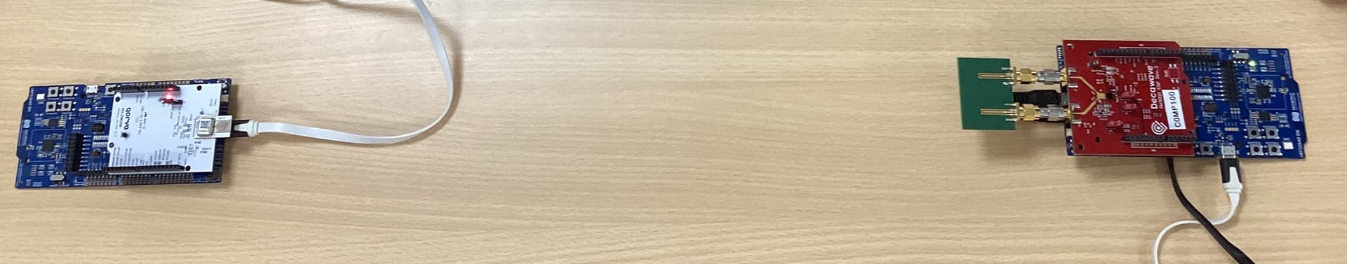
The hardware setup is as what I mentioned above.
As mentioned in the previous post, the result we got from the anchor is fluctuation which is unable to calculate the average. The value is from 0~100 cm.(the whole setup is still)
I was told to calibrate the whole set. After calibartion by using the following tool,
still the result is the same with larget fluctuation.
…\DW3xxx_XR6.0C_24Feb2022\Release_XR6.0C\Software\DW3XXX_DecaRanging\Bin\DecaRanging_5p02.exe
From the environment setting and FW that we used, is there anything missing or wrong here?
Thanks a lot for your help indeed.
- Use pre-compiled binaries from the XR codebase. They should bi in the original zip in the bin folder.
- Which antennas do you use on the AoA chip?
- Which antenna do you use on the non-AoA chip?
- Which uwb config did you set on both boards to run tests?
- Did you change anything from the default values?
You should provide as much info, better with fotos, screenshoots and steps to replicate, as you can if you want to get better help.
I believe Qorvo support team is periodically looking to the forum and would try to understand/reproduce the anomaly, so the best you can give them the input data, the easier would be to understand what is wrong.
I personally having only 2 dwm3000evb, which are non-AoA, and on that XR6 release i have 2.5cm std dev…
Thanks again for any possible suggestions.
-
Use pre-compiled binaries from the XR codebase. They should be in the original zip in the bin folder.
→ Use the original hex file give the same result. – still fluctuation. -
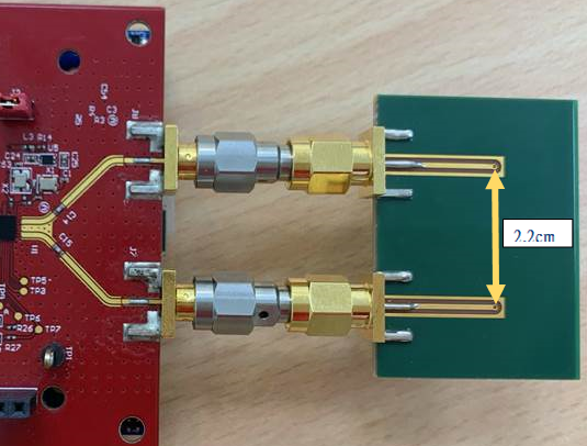
Which antennas do you use on the AoA chip?
→ The original EVB antenna is used in the test. The following is the setup I used for tag.
-
Which antenna do you use on the non-AoA chip?
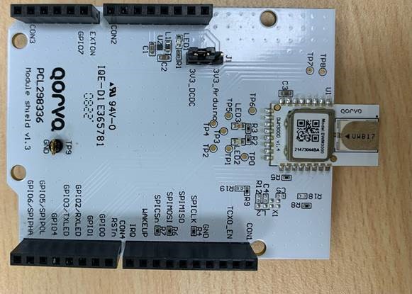
→ The original EVB antenna is used in the test. The following is the setup I used for anchor.
-
Which uwb config did you set on both boards to run tests?
→ DWM3000EVB with nRF52840-DK setup as tag. No need to setup any mode.
→ QM33120WDK2.0 with nRF52840-DK uses PDoA. Use non-AoA mode. -
Did you change anything from the default values?
→ No changes, just uses the default values.
1 Like
Some thoughts:
-
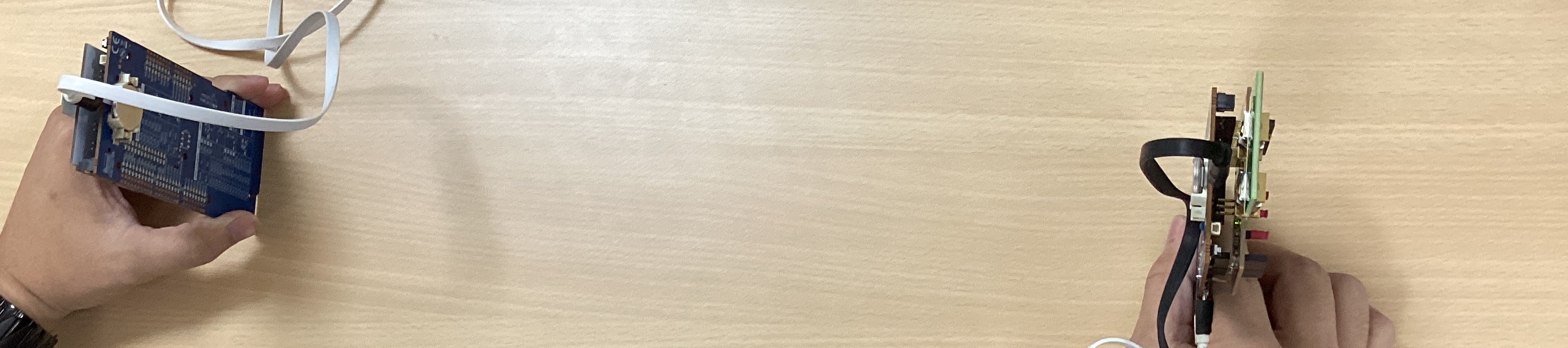
When testing, how you position boards? The radiated elements on AoA antenna look like two circles and they are directional.
-
If swap roles, would that improve TWR?
Just overlooked. You set a non-AoA mode on AoA chip, so PdoA_mode is set to 0, right?
But if use PDoA 1 or 3, does that improve TWR?
Thanks again for any possible suggestions.
- I tried both ways to test (horizontal and vertical), but still the same result. (The measured distance fluctuated in the range of 0-100. )
-
Swap roles, it did have stable result.
[scenario 2] Stable measured result.
→ DWM3000EVB(DW3110) with nRF52840-DK setup as anchor.
→ QM33120WDK2.0(DW3120) with nRF52840-DK setup as tag.
In this scenario, the whole setup runs under AoA.[scenario 1] Fluctuated measured result.
→ DWM3000EVB(DW3110) with nRF52840-DK setup as tag.
- No change any other values.
→ QM33120WDK2.0 with nRF52840-DK setup as anchor.
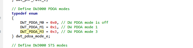
- Use PDoA mode 1 or mode 3.
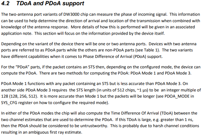
In this scenario, the whole setup is expected to run under PDoA and we could select mode1 or mode3.
From the section 4.2 of DW3000 Data Sheet, it tells the differences between mode1 and mode3. Mode 3 shold have higher accuracy than mode1.
But from the measurement result, it seems PDoA is not activated in scenario 1.
- → DWM3000EVB(DW3110) with nRF52840-DK setup as tag.
→ QM33120WDK2.0(DW3120) with nRF52840-DK setup as anchor.
I tried both PDoA mode M1 and M3.
The measured distance still fluctuated in the range of 0-100.
Hi Yin,
I have a few points:
-
XR6.0 is older version of FW and we are not actively supporting it. Either way, it should still perform OK. You can download our latest QM33-DK from the Qorvo website:
QM33120WDK1 - Qorvo -
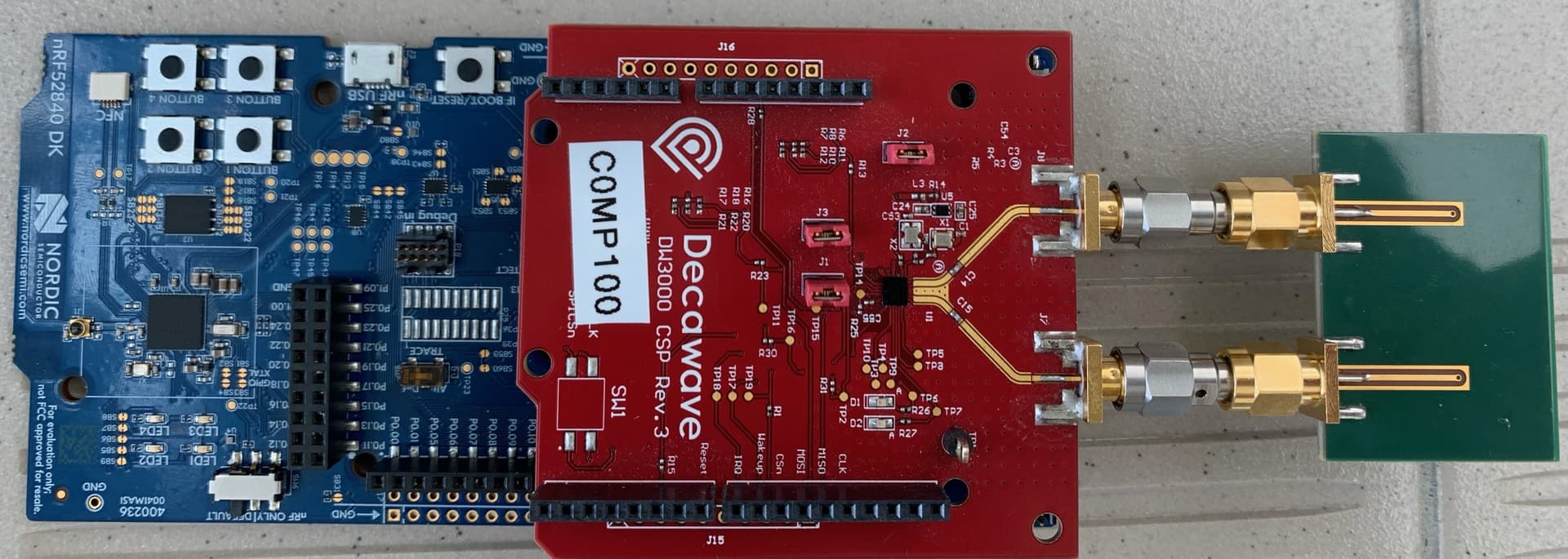
In your photo you are showing DWM3000EVB and DW3120EVB. You do not have a QM33120WDK. These will both work with the latest QM33-DK
-
The ranging issues are likely due to the USB cable coming out of the top of the NRF52840 board. They are only needed for programming the board and then the should be removed to get the best ranging performance.
1 Like
Hi Yin,
Some further comments:
- You write:
In this scenario, the whole setup runs under AoA.
In this scenario, the whole setup is expected to run under PDoA and we could select mode1 or mode3.
There is no such thing as AoA mode or PDoA mode.
The Angle of Arrival (AoA) is computed by measuring the Phase Difference of Arrival (PDoA) and mapping it to an angle via a look-up table, which has been characterised in the lab for the specific antenna.
In your two scenarios, you have swapped the roles of tag and anchor between the DWM3000EVB and the DW3120EVB.
If the DWM3000EVB is set as the anchor, you cannot get PDoA/AoA measurement, as there is only one antenna on this board.
If the DW3120EVB is set as the anchor, then you need to make sure that pdoa_mode is set to 1 or 3 to enable PDoA/AoA measurment.
If you set the pdoa_mode to 0, then the DW3120 will only perform ranging with a single antenna, so you will not get PDoA/AoA measurement.
1 Like
@tmc_qrvo
Appreciate your comments on my post.
- XR6.0 is older version of FW and we are not actively supporting it. Either way, it should still perform OK. You can download our latest QM33-DK from the Qorvo website:
QM33120WDK1 - Qorvo
Will try this and see how it goes.
- In your photo you are showing DWM3000EVB and DW3120EVB. You do not have a QM33120WDK. These will both work with the latest QM33-DK
One of the board I used is QM33-DK (QM33120WDK2.0).(red board only) I believe so…
It is hard to compare the board I got with the board from QM33120WDK1 Quick Start Guide document. The picture in QM33120WDK1 Quick Start Guide is way too blur…
If below picture(red board) is not QM33120WDK2.0, please let me know.
I switched the main board to nRF52840-DK.
- The ranging issues are likely due to the USB cable coming out of the top of the NRF52840 board. They are only needed for programming the board and then the should be removed to get the best ranging performance.
Thanks for pointing this out.
I will try to power it up from the other power source and give it a try.
@tmc_qrvo
Thanks again for providing suggestions.
[scenario 2] Stable measured result.
→ DWM3000EVB(DW3110) with nRF52840-DK setup as anchor.
→ QM33120WDK2.0(DW3120) with nRF52840-DK setup as tag.
In this scenario, the whole setup runs under AoA.
Sorry for the confusion here. For scenairo 2, it should be non-AoA.
If the DWM3000EVB is set as the anchor, you cannot get PDoA/AoA measurement, as there is only one antenna on this board.
If the DW3120EVB is set as the anchor, then you need to make sure that pdoa_mode is set to 1 or 3 to enable PDoA/AoA measurment.
If you set the pdoa_mode to 0, then the DW3120 will only perform ranging with a single antenna, so you will not get PDoA/AoA measurement.
Just like you say, it is non AoA if DWM3000EVB is set as the anchor. [Scenario 2]
As for [Scenario 1], it is expected to be PDoA since I used 2 antennas and set the pdoa_mode to 1 or 3.
Thanks for any possible suggestions.
The Angle of Arrival (AoA) is computed by measuring the Phase Difference of Arrival (PDoA) and mapping it to an angle via a look-up table, which has been characterised in the lab for the specific antenna.
Is there any document to guide us to setup this look-up table if I change the antenna design?
Or I could just ignore this look-up table even after I change the antenna ?
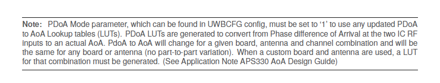
I found one note from page 27 in DW3QM33_SDK_Developer_Guide_0.1.1.pdf.
It mentions a LUT should be generated if one uses customized board and antenna.
It also mentions the document Application Note APS330 AoA Design Guide.
However, I can not find this document. Could anyone provide the resource of this document?
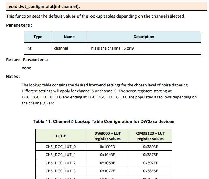
The following information was found on page47 in DW3xxx_Driver_API_Guide_6.0.14.pdf ( QM33120WDK1 - Qorvo )
I am not sure if this one is the LUT that you mentioned. However, I can not find any way to change this in this document, either.
@tmc_qrvo
I tried QM33120WDK1 - Qorvo
The output result shows as below.
I am not sure how to covert these parameters, "D_cm":17,"LPDoA_deg":30.88,"LAoA_deg":11.63,, into x, y.
Any suggestion is welcomed.
{"Block":3676, "results":[{"Addr":"0x0000","Status":"Ok","D_cm":40,"LPDoA_deg":50.49,"LAoA_deg":19.02,"LFoM":205,"RAoA_deg":0.00,"CFO_100ppm":-551}]}
{"Block":3677, "results":[{"Addr":"0x0000","Status":"Ok","D_cm":42,"LPDoA_deg":46.49,"LAoA_deg":17.48,"LFoM":205,"RAoA_deg":0.00,"CFO_100ppm":-552}]}
{"Block":3678, "results":[{"Addr":"0x0000","Status":"Ok","D_cm":34,"LPDoA_deg":41.35,"LAoA_deg":15.50,"LFoM":205,"RAoA_deg":0.00,"CFO_100ppm":-573}]}
{"Block":3679, "results":[{"Addr":"0x0000","Status":"Ok","D_cm":40,"LPDoA_deg":41.87,"LAoA_deg":15.69,"LFoM":215,"RAoA_deg":0.00,"CFO_100ppm":-560}]}
{"Block":3680, "results":[{"Addr":"0x0000","Status":"Ok","D_cm":38,"LPDoA_deg":40.17,"LAoA_deg":15.05,"LFoM":205,"RAoA_deg":0.00,"CFO_100ppm":-542}]}
{"Block":3681, "results":[{"Addr":"0x0000","Status":"Ok","D_cm":42,"LPDoA_deg":39.78,"LAoA_deg":14.88,"LFoM":205,"RAoA_deg":0.00,"CFO_100ppm":-539}]}
{"Block":3682, "results":[{"Addr":"0x0000","Status":"Ok","D_cm":41,"LPDoA_deg":45.37,"LAoA_deg":17.03,"LFoM":126,"RAoA_deg":0.00,"CFO_100ppm":-569}]}
{"Block":3683, "results":[{"Addr":"0x0000","Status":"Ok","D_cm":42,"LPDoA_deg":54.38,"LAoA_deg":20.53,"LFoM":156,"RAoA_deg":0.00,"CFO_100ppm":-570}]}
{"Block":3684, "results":[{"Addr":"0x0000","Status":"Ok","D_cm":39,"LPDoA_deg":59.39,"LAoA_deg":22.46,"LFoM":215,"RAoA_deg":0.00,"CFO_100ppm":-505}]}
{"Block":3685, "results":[{"Addr":"0x0000","Status":"Ok","D_cm":17,"LPDoA_deg":30.88,"LAoA_deg":11.63,"LFoM":235,"RAoA_deg":0.00,"CFO_100ppm":-570}]}
{"Block":3686, "results":[{"Addr":"0x0000","Status":"Ok","D_cm":19,"LPDoA_deg":2.09,"LAoA_deg":0.78,"LFoM":235,"RAoA_deg":0.00,"CFO_100ppm":-555}]}
{"Block":3687, "results":[{"Addr":"0x0000","Status":"Ok","D_cm":28,"LPDoA_deg":-34.07,"LAoA_deg":-12.64,"LFoM":225,"RAoA_deg":0.00,"CFO_100ppm":-542}]}
{"Block":3688, "results":[{"Addr":"0x0000","Status":"Ok","D_cm":21,"LPDoA_deg":-110.36,"LAoA_deg":-40.81,"LFoM":225,"RAoA_deg":0.00,"CFO_100ppm":-551}]}
{"Block":3689, "results":[{"Addr":"0x0000","Status":"Ok","D_cm":21,"LPDoA_deg":-113.97,"LAoA_deg":-42.15,"LFoM":225,"RAoA_deg":0.00,"CFO_100ppm":-534}]}
{"Block":3690, "results":[{"Addr":"0x0000","Status":"Ok","D_cm":22,"LPDoA_deg":-122.78,"LAoA_deg":-45.54,"LFoM":225,"RAoA_deg":0.00,"CFO_100ppm":-554}]}
{"Block":3691, "results":[{"Addr":"0x0000","Status":"Ok","D_cm":27,"LPDoA_deg":-128.27,"LAoA_deg":-47.58,"LFoM":225,"RAoA_deg":0.00,"CFO_100ppm":-546}]}
{"Block":3692, "results":[{"Addr":"0x0000","Status":"Ok","D_cm":24,"LPDoA_deg":-134.87,"LAoA_deg":-50.13,"LFoM":225,"RAoA_deg":0.00,"CFO_100ppm":-546}]}
In the document, DW3QM33_SDK_Developer_Guide_0.1.1.pdf, the following information is the only relevent I found, but it still doe not show us how to convert to x,y.

HI Yin,
The registers you are looking at have nothing to do with AoA. You should not modify the values in side those.
To calculate X, Y, you simply need to do some trigonometric calculations.
If you know the angle (“LAoA_deg”) and the distance (“D_cm”), then you can easily calculate X and Y.