DW3000, how to do ranging in PDOA mode 3?

Hi!

I’m trying to modify and run the example code for two-way ranging (ds_twr_initiator_sts.c and ds_twr_responder_sts.c) so they work in PDOA mode 3. But the ranging always fails. It seems that some extra modification is needed for this mode.
Could anyone please suggest what needs to be modified in this case, or which manual I can refer to regarding PDOA mode 3?

Thanks in advance!

HI @BC0023 ,

PDOA mode 3 required STS length to be an integer multiple of 128 (128, 25, 512).
Is this a configuration you already changed in the example?

Hi @Wassim_Qorvo

Yes, I have tried both 128 and 256, but no success.

Can you send the uwb configuration you’ve set in the example?
Also, can you tell what boards you’re using for this test?

Hi @Wassim_Qorvo

I’m using QM33120WDK1 kit (QM33110WEVB+nRF52840DK).

Here’s the uwb configuration:

static dwt_config_t config = {
5, // Channel number.
DWT_PLEN_128, // Preamble length. Used in TX only.
DWT_PAC8, // Preamble acquisition chunk size. Used in RX only.
9, // TX preamble code. Used in TX only.
9, // RX preamble code. Used in RX only.
1, // 0 to use standard 8 symbol SFD, 1 to use non-standard 8 symbol, 2 for non-standard 16 symbol SFD and 3 for 4z 8 symbol SDF type
DWT_BR_6M8, // Data rate.
DWT_PHRMODE_STD, // PHY header mode.
DWT_PHRRATE_STD, // PHY header rate.
(129 + 8 - 8), // SFD timeout (preamble length + 1 + SFD length - PAC size). Used in RX only.
(DWT_STS_MODE_1 | DWT_STS_MODE_SDC),
DWT_STS_LEN_128, // STS length see allowed values in Enum dwt_sts_lengths_e
DWT_PDOA_M3 // PDOA mode 3
};

Thanks!

Hi @BC0023 ,

I succeed on my side to do ranging using PDoA mode 3 with the configuration below:
#ifdef CONFIG_OPTION_33
/* Configuration option 33.

  • Channel 5, PRF 64M, Preamble Length 128, PAC 8, Preamble code 9, Data Rate 6.8M, STS Length 128
    /
    dwt_config_t config_options = {
    5, /
    Channel number. /
    DWT_PLEN_128, /
    Preamble length. Used in TX only. /
    DWT_PAC8, /
    Preamble acquisition chunk size. Used in RX only. /
    9, /
    TX preamble code. Used in TX only. /
    9, /
    RX preamble code. Used in RX only. /
    3, /
    0 to use standard 8 symbol SFD, 1 to use non-standard 8 symbol, 2 for non-standard 16 symbol SFD and 3 for 4z 8 symbol SDF type /
    DWT_BR_6M8, /
    Data rate. /
    DWT_PHRMODE_STD, /
    PHY header mode. /
    DWT_PHRRATE_STD, /
    PHY header rate. /
    (128 + 1 + 8 - 8), /
    SFD timeout (preamble length + 1 + SFD length - PAC size). Used in RX only. /
    DWT_STS_MODE_1, /
    Mode 1 STS enabled /
    DWT_STS_LEN_128, /
    (STS length in blocks of 8) - 1*/
    DWT_PDOA_M3 /* PDOA mode off */
    };

I see that you’re setting SFD to 1. This field should be 3 when using STS.

Hi @Wassim_Qorvo
Now it is working. Many thanks!

Hi @Wassim_Qorvo

Could you please also help to explain a bit about the PDOA offset as well?
In the API guide, dwt_readpdoaoffset returns a uint16_t value, and it says this value is in DWT_TIME_UNITS (15.65 picoseconds ticks). I have no idea how to convert this value into an angle (rad).


Thanks in advance!

Hi @BC0023 ,

I would suggest that you see the implementation of PDOA_offset function in the QM33 SDK available in the website: https://www.qorvo.com/products/d/da008582

Check the code below:
{ // PDoA offset
if (dw->mcps_runtime->pdoa_offset < 0)
{
tmp = (int)(-1 * (dw->mcps_runtime->pdoa_offset) * M_PI) * (1 << 11) / 180;
}
else if (dw->mcps_runtime->pdoa_offset > 0)
{
tmp = (int)((360 - dw->mcps_runtime->pdoa_offset) * M_PI) * (1 << 11) / 180;
}
else
{
tmp = 0;
}

    dw->dwt_driver->dwt_ops->ioctl(dw, DWT_SETPDOAOFFSET, 0, (void *)&tmp);
}

Thanks! @Wassim_Qorvo

Hi @Wassim_Qorvo !

In the example of ds_twr_responder_sts.c, I added code for reading diagnosis data (CIR and PDOA basically). The code is running fine in PDOA mode 3 with your help. I compared the PDOA read directly with dwt_readpdoa, and the PDOA I calculated with CIR imaginary and real part. They are almost the same. So I guess I’m getting the correct PDOA.

However, when I calculate AOA from the PDOA (arcsin(PDOA_rad/pi*0.5/0.45), I always get AOA estimations near zero, even if the actual AOA is 4/pi. If I read the measurements from the virtual COM port in UCI at the same distance and same angle, it actually gives good AOA estimations.

I’ve tried varying the actual AOA from -pi/4 to pi/4. The calculated AOA from PDOA is always nearly 0.
Could you please suggest what might be wrong or missing here?

Thanks!

Hi @Wassim_Qorvo

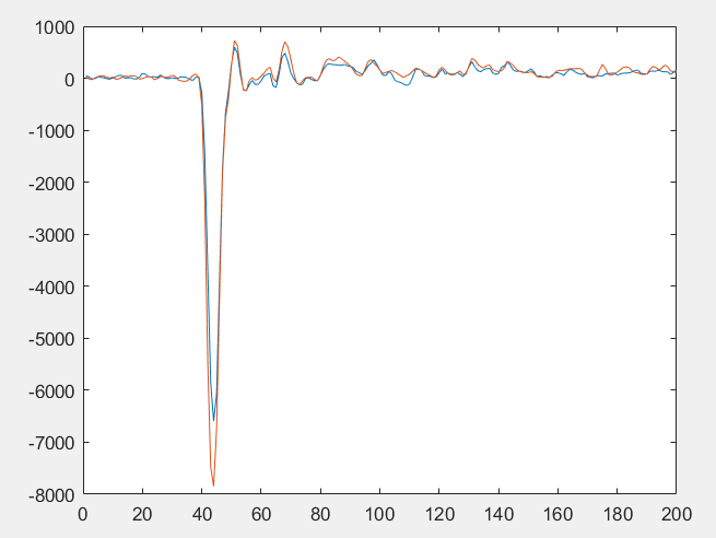
I did some further analysis. It seems that in PDOA mode 3, the CIRs of STS and STS2 are very similar for both the imaginary and real parts. For example, the figure below shows the real part of STS and STS2 CIRs (last 200 samples). I guess that is why the PDOA is small and results in an AOA close to 0.
Do you maybe have any idea why this happens?
Thanks!
image