Hi There!
We have developed a very simple board that uses a DW1001 module, an ESP32 board for remote updating, and a DC-DC power supply module so we can use LiPo batteries (3.7-4.2v) to drive the board
The DC-DC is based on the module TPS63021DSJR.
Scenario 1: When the module is powered off a LiPo battery to the DC-DC module, we get(correct) low power consumption (lasting 4-5 months) but the module is inaccurate and the DW signal seems intermittent. If we use the Android APK, the connecting lines in the grid view are flickeringf all the time and the position swifts more than acceptable.
Scenario 2: We apply power directly to the Vreg side in the circuit (output of the DC-DC converter so we bypass it), in this case with a LiFePO4 battery (se we stay at a safe 3.3v), now the accuracy is 100%, no flicker in the connecting lines in the grid view. (weird side effect is that we get 175mA consumption whoch we still don’t undestand, but thats not the thing now).
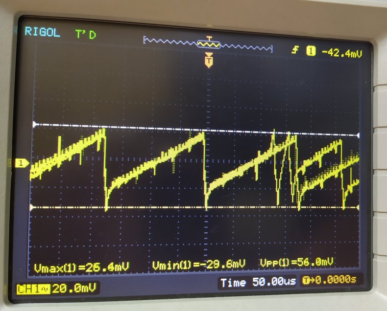
Ive used an oscilloscope to measure the dc-dc ps output when in use and I get a 60mv Vpp saw tooth shape in the Vreg line. Is this enough ripple to make the DW1001 loose data and show those flickering lines in the grid view?
Thanks!
While I find out whether I can disclose the schematic (as I signed an NDA for this project), I can share the PS output plot.
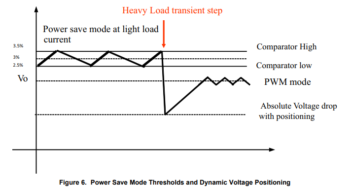
Also the PS, like I said, is based on the TPS63021 voltage regulator with basically the same components they suggest in their datasheet (same caps, resistors, coil), but with PS/SYNC connected to GND instead of HIGH (Thus, Power Save mode is activated).
PS ON get actually activated below 100mA outout, which is the normal condition for this device.
I was wondering maybe PS ON means worse current stabilization accuracy, so this would be a point to check
Also I don’t want to bias the possible reasons, as RF interference between the PS regultor and the DW module could also be a reason, right?
So is easy, the problem is the selected regulator, the regulator is working well, that noise that you see is the standard output ripple for low power mode, in PWM you can reduce a little bit the noise, but is still noisy. also you are choosing a buck boost regulator (stepUp/StepDown) not the best kind of regulator for this application.
So the recommendations are:
For Ultra Low Noise in anchors Follow the next topology e.g. 24V-> DC-DC(5V) → Linear (3.3V), use a step down regulator to down the high input voltage, and then a LDO with a high PSRR (Power Supply Ripple Rejection) for example you can use the TPS7A4700 it has a super low noise ouput Output Voltage Noise:4 µVRMS (10 Hz, 100 kHz) + a super High Ripple Rejection (PSRR): 82 dB (100 Hz)
*For tags always focus on three factors
“Low Quiescent Current”
“High Efficiency”
“LowNoise/HighPSRR”
*For Step Down in tags (LiPo or Similar) I recommend the “TPS62842”, Iq=60nA
*For Step Up in tags (AA/AAA or similar) I recommend the “TPS613221” , Iq=6.5uA
Very Useful amigo!
In this case the anchor (this is the one we are having issues with) is also running on batteries. Does this matter? I mean you mentioned different regulator for tags and for anchors
Specifically running on LiPo batteries so our voltage would need to be stepped down. Is TPS62842 still advised?
I truly appreciate your help and time!
EDIT!!! We’re not using LiPo (4.2v) but Li-Ion batteries running at 3.6V
And it’s the tags (not anchors) the ones having the issue (anchors are running off 220V power supplies)
the voltage difference is very small, you can share the discharge curve of the battery that help to decide which topology is best boost or buck, also the TPS613221 operates as a LDO regulator when Vin>Vout (but the efficiency in the LDO mode is small).
Thanks again. At this point we are revieing the PS section again. The board contains not only a DWM1001 module but also a ESP32Wroom module, so we need to find out if 750mA is going to be enough for the expected current peaks in these 2 modules together