DW1000 struggles with receiving packets, Channel Impulse Response is off

I have some problems getting the DWM1000 module to work (as I have discussed in another topic).

This time I have a module that doesn’t have a CLKPLL_LL error (or any error at all, really) but it has problems receiving packets from another DWM1000, which is 3m away.
It doesn’t receive nearly all the packets (maybe ever 3rd packet if I am lucky) and the Channel Impulse Resopnse (that’s what I am after actually) looks off, this means it is very noisy:

Comparison of CIRs from a healthy and faulty device

If I replace the DWM1000 module with another DWM1000, the CIR looks way smoother and better (as you can see in the image above). So I assume this is a problem with that specific DWM1000 module.

My setup:

DWM1000 is connected to a Raspberry Pi 4 (this means SPI and 3.3V and GND) via a breadboard-type setup. I soldered a 100µF ceramic 1205, a 22µF ceramic 0805 and a 400µF electrolytic capacitor to the GND and VCC pins of the DWM1000 (so very close to the chip itself). The antenna is hovering over the breadboard and over the Raspberry Pi so there is no metallic service close to it that could disturb the signal.

What could cause this behavior? Any ideas how to fix it?

Are you reading the XTAL tune value from the OTP and applying it?
I assume that is the CIR data from multiple packets all joined together. If that’s from a single reception then you have something very odd going on, there should only be one strong peak followed by some reflections. You shouldn’t get a repetitive pattern like that.

1 Like

Yes sorry, those are multiple packets after another. Each major peak is one packet.

Regarding XTAL-OTP: Do you mean LDOTUNE? This is basically all the setup I am doing:

        DEV_ID = self.read(reg_addr=0x00, sub_reg_addr=0x00, len=4)
        print(
            f"Device-ID: REV: {DEV_ID[0] & 0x0F}, VER: {DEV_ID[0] >> 3}, MODEL: {DEV_ID[1]}, RIDTAG: {hex(DEV_ID[3] << 8 | DEV_ID[2])}")

        self.write(reg_addr=0x23, sub_reg_addr=0x04, data=[0x70, 0x88])
        AGC_TUNE1 = self.read(reg_addr=0x23, sub_reg_addr=0x04, len=2)
        print(f"Modified AGC_TUNE1 to {hex(AGC_TUNE1[1] << 8 | AGC_TUNE1[0])}")

        self.write(reg_addr=0x23, sub_reg_addr=0x0C, data=[0x07, 0xA9, 0x02, 0x25])
        AGC_TUNE2 = self.read(reg_addr=0x23, sub_reg_addr=0x0C, len=4)
        print(
            f"Modified AGC_TUNE2 to {hex(AGC_TUNE2[3] << 24 | AGC_TUNE2[2] << 16 | AGC_TUNE2[1] << 8 | AGC_TUNE2[0])}")

        self.write(reg_addr=0x23, sub_reg_addr=0x12, data=[0x35, 0x00])
        AGC_TUNE3 = self.read(reg_addr=0x23, sub_reg_addr=0x12, len=2)
        print(f"Modified AGC_TUNE3 to {hex(AGC_TUNE3[1] << 0 | AGC_TUNE3[0])}")

        self.write(reg_addr=0x27, sub_reg_addr=0x00, data=[0x01, 0x00])
        DRX_TUNE0b = self.read(reg_addr=0x27, sub_reg_addr=0x00, len=2)
        print(f"Modified DRX_TUNE0b to {hex(DRX_TUNE0b[1] << 8 | DRX_TUNE0b[0])}")

        self.write(reg_addr=0x27, sub_reg_addr=0x04, data=[0x87, 0x00])
        DRX_TUNE1a = self.read(reg_addr=0x27, sub_reg_addr=0x04, len=2)
        print(f"Modified DRX_TUNE1a to {hex(DRX_TUNE1a[1] << 8 | DRX_TUNE1a[0])}")

        self.write(reg_addr=0x27, sub_reg_addr=0x06, data=[0x10, 0x00])
        DRX_TUNE1b = self.read(reg_addr=0x27, sub_reg_addr=0x06, len=2)
        print(f"Modified DRX_TUNE1b to {hex(DRX_TUNE1b[1] << 8 | DRX_TUNE1b[0])}")

        self.write(reg_addr=0x27, sub_reg_addr=0x08, data=[0x2D, 0x00, 0x1A, 0x31])
        DRX_TUNE2 = self.read(reg_addr=0x27, sub_reg_addr=0x08, len=4)
        print(
            f"Modified DRX_TUNE2 to {hex(DRX_TUNE2[3] << 24 | DRX_TUNE2[2] << 16 | DRX_TUNE2[1] << 8 | DRX_TUNE2[0])}")

        self.write(reg_addr=0x27, sub_reg_addr=0x26, data=[0x10, 0x00])
        DRX_TUNE4H = self.read(reg_addr=0x27, sub_reg_addr=0x26, len=2)
        print(f"Modified DRX_TUNE4H to {hex(DRX_TUNE4H[1] << 8 | DRX_TUNE4H[0])}")

        self.write(reg_addr=0x2E, sub_reg_addr=0x0806, data=[0x3D])
        NTM = self.read(reg_addr=0x2E, sub_reg_addr=0x0806, len=1)
        print(f"Modified NTM to {hex(NTM[0])}")

        self.write(reg_addr=0x2E, sub_reg_addr=0x1806, data=[0x07, 0x16])
        LDE_CFG2 = self.read(reg_addr=0x2E, sub_reg_addr=0x1806, len=2)
        print(f"Modified LDE_CFG2 to {hex(LDE_CFG2[1] << 8 | LDE_CFG2[0])}")

        self.write(reg_addr=0x1E, sub_reg_addr=0x00, data=[0x48, 0x28, 0x08, 0x0E])
        TX_POWER = self.read(reg_addr=0x1E, sub_reg_addr=0x00, len=4)
        print(f"Modified TX_POWER to {hex(TX_POWER[3] << 24 | TX_POWER[2] << 16 | TX_POWER[1] << 8 | TX_POWER[0])}")

        self.write(reg_addr=0x28, sub_reg_addr=0x0C, data=[0xE3, 0x3F, 0x1E, 0x00])
        RF_TXCTRL = self.read(reg_addr=0x28, sub_reg_addr=0x0C, len=4)
        print(
            f"Modified RF_TXCTRL to {hex(RF_TXCTRL[3] << 24 | RF_TXCTRL[2] << 16 | RF_TXCTRL[1] << 8 | RF_TXCTRL[0])}")

        self.write(reg_addr=0x2A, sub_reg_addr=0x0B, data=[0xB5])
        TC_PGDELAY = self.read(reg_addr=0x2A, sub_reg_addr=0x0B, len=1)
        print(f"Modified TC_PGDELAY to {hex(TC_PGDELAY[0])}")

        self.write(reg_addr=0x2B, sub_reg_addr=0x07, data=[0x1D, 0x04, 0x00, 0x08])
        FS_PLLCFG = self.read(reg_addr=0x2B, sub_reg_addr=0x07, len=4)
        print(
            f"Modified FS_PLLCFG to {hex(FS_PLLCFG[3] << 24 | FS_PLLCFG[2] << 16 | FS_PLLCFG[1] << 8 | FS_PLLCFG[0])}")

        self.write(reg_addr=0x2B, sub_reg_addr=0x0B, data=[0xBE])
        FS_PLLTUNE = self.read(reg_addr=0x2B, sub_reg_addr=0x0B, len=1)
        print(f"Modified FS_PLLTUNE to {hex(FS_PLLTUNE[0])}")

        EC_CTRL = self.read(reg_addr=0x24, sub_reg_addr=0x00, len=4)
        EC_CTRL[0] |= (1 << 2)  # Clock PLL lock detect
        self.write(reg_addr=0x24, sub_reg_addr=0x00, data=EC_CTRL)

        # PLL Config
        RF_CONF = self.read(reg_addr=0x28, sub_reg_addr=0x00, len=4)
        RF_CONF[1] |= (1 << 7) | (1 << 6) | (1 << 5)  # Enable CLK_PLL and RF_PLL
        # RF_CONF[2] |= (1 << 5)  # Configure for RX
        self.write(reg_addr=0x28, sub_reg_addr=0x00, data=RF_CONF)

        # Set LDELOAD for timestamp information as Receiver according to 2.5.5.10
        PMSC_CTRL0 = self.read(reg_addr=0x36, sub_reg_addr=0x00, len=4)
        OTP_CTRL = self.read(reg_addr=0x2D, sub_reg_addr=0x06, len=2)

        PMSC_CTRL0[0] = 0x01
        PMSC_CTRL0[1] = 0x03
        OTP_CTRL[0] = 0x00
        OTP_CTRL[1] = 0x80
        self.write(reg_addr=0x36, sub_reg_addr=0x00, data=PMSC_CTRL0)
        self.write(reg_addr=0x2D, sub_reg_addr=0x06, data=OTP_CTRL)

        time.sleep(0.01)

        PMSC_CTRL0 = self.read(reg_addr=0x36, sub_reg_addr=0x00, len=4)
        PMSC_CTRL0[0] = 0x00
        PMSC_CTRL0[1] = 0x02

        self.write(reg_addr=0x36, sub_reg_addr=0x00, data=PMSC_CTRL0)

        # Check if LDOTUNE was calibrated according to 6.3.3
        self.write(reg_addr=0x2D, sub_reg_addr=0x04, data=[0x04, 0x00])
        self.write(reg_addr=0x2D, sub_reg_addr=0x06, data=[0x03])
        self.write(reg_addr=0x2D, sub_reg_addr=0x06, data=[0x00])
        OTP_LDOTUNE = self.read(reg_addr=0x2D, sub_reg_addr=0x0A, len=4)
        if OTP_LDOTUNE[0] != 0:
            self.write(reg_addr=0x28, sub_reg_addr=0x30, data=OTP_LDOTUNE)
            OTP_LDOTUNE = self.read(reg_addr=0x28, sub_reg_addr=0x30, len=4)
            print(
                f"Modified LDOTUNE to {hex(OTP_LDOTUNE[3] << 24 | OTP_LDOTUNE[2] << 16 | OTP_LDOTUNE[1] << 8 | OTP_LDOTUNE[0])}")
        else:
            print("LDOTUNE value has not been set.")
No. By XTAL OTP I mean XTAL_Trim, a 5 bit values stored at memory address 0x1E in the OTP.
This value should be copied to Sub-Register 0x2B:0E – FS_XTALT

For modules this OTP value should have been set at the factory.

1 Like

Hi,

I am attempting to calculate the distance, but I am receiving incorrect results, and the distance is showing as negative. Here is the code for distance calculation:

static void rx_ok_cb(const dwt_cb_data_t *cb_data)
{
uint32 frame_len;

/* Clear good RX frame event in the DW1000 status register. */
dwt_write32bitreg(SYS_STATUS_ID, SYS_STATUS_RXFCG);

/* A frame has been received, read it into the local buffer. */
frame_len = dwt_read32bitreg(RX_FINFO_ID) & RX_FINFO_RXFLEN_MASK;

/* Clear local RX buffer to avoid having leftovers from previous receptions. This is not necessary but is included here to aid reading the RX
 * buffer. */
for (int i = 0 ; i < frame_len; i++ )
{
	rx_buffer[i] = 0;
}

if (frame_len <= RX_BUF_LEN)
{
	dwt_readrxdata(rx_buffer, frame_len, 0);
}

/* Check that the frame is the expected response from the companion "SS TWR responder" example.
 * As the sequence number field of the frame is not relevant, it is cleared to simplify the validation of the frame. */
rx_buffer[ALL_MSG_SN_IDX] = 0;
if (memcmp(rx_buffer, rx_resp_msg, ALL_MSG_COMMON_LEN) == 0)
{
	uint32 poll_tx_ts, resp_rx_ts, poll_rx_ts, resp_tx_ts;
	int32 rtd_init, rtd_resp;
	float clockOffsetRatio ;

	/* Retrieve poll transmission and response reception timestamps. See NOTE 9 below. */
	poll_tx_ts = dwt_readtxtimestamplo32();
	resp_rx_ts = dwt_readrxtimestamplo32();

	/* Read carrier integrator value and calculate clock offset ratio. See NOTE 11 below. */
	clockOffsetRatio = dwt_readcarrierintegrator() * (double)((FREQ_OFFSET_MULTIPLIER * HERTZ_TO_PPM_MULTIPLIER_CHAN_2) / 1.0e6) ;

	/* Get timestamps embedded in response message. */
	resp_msg_get_ts(&rx_buffer[RESP_MSG_POLL_RX_TS_IDX], &poll_rx_ts);
	resp_msg_get_ts(&rx_buffer[RESP_MSG_RESP_TX_TS_IDX], &resp_tx_ts);

	/* Compute time of flight and distance, using clock offset ratio to correct for differing local and remote clock rates */
	rtd_init = resp_rx_ts - poll_tx_ts;
	rtd_resp = resp_tx_ts - poll_rx_ts;

	tof = ((rtd_init - rtd_resp * (1.0f - (double)clockOffsetRatio)) / 2.0f) * DWT_TIME_UNITS;
	distance = (tof * SPEED_OF_LIGHT);
            }
     /* Set corresponding inter-frame delay. */
tx_delay_ms = DFLT_TX_DELAY_MS;

}…

How negative?
Is it a constant offset from truth? If you move them 1m further apart does the value increase by 1m?
If it looks like a constant error then it could simply be an antenna calibration issue.

The other common one is are you applying the clock offset ratio in the correct direction? It’s very easy to correct things in the wrong direction. (it’s been long enough since I looked at that code that I can’t remember if you have it the correct way or not)

Is it always short or only some of the time? If some of the time what’s your environment like? There are some situations where you can get an incorrect short measurement due to odd reflections. This is a long shot, those environments are fairly rare - large hangers or long straight tunnels.

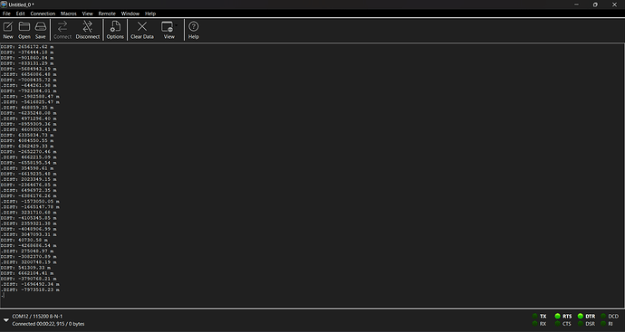
Hi, this is my result:

I don’t have any idea to correct this. Please, help me out in this.

So you’ve effectively got a random number generator there, you are getting values of +/- thousands of km.

rtd_init and rtd_resp should be unsigned. You are only using the low 32 bits of the time, from memory that will wrap around every ~70 ms. If you do a signed calculation of the difference when that happens you’ll get bad results.
But that’s a corner case, you wouldn’t get that every range.

I can’t see any obvious issues.
If the maths is giving junk then either the inputs are junk or the calculations are wrong. So check the inputs.
I’d start by outputting the 4 timestamp values and the two rtd_ values and sanity checking those numbers. Based on that dig further into anything that looks wrong. You can always pull the time now out of the DW1000 and also output that, you can then check that the local rx and tx times are sensible. If the remote time differences looks wrong (it should be your intended delay time) then connect to the serial output on the anchor and get it to also output the times, check that they match the ones you are reading at the tag and that they are also sensible. Possibly output the full contents of the Rx packet and check it is correctly formatted.

Hopefully it’s something simple like one time value being obviously wrong. If you read times at the wrong point (e.g. read the Rx timestamp after re-arming the receiver) then you’ll get junk values, a pain but once you find it easy to fix.

Thank you for your response, @AndyA . I will try this and then get back to you.

I calibrated the antenna delay of the DW1000 module. However, whenever I attempt to measure a distance less than 1 meter or greater than 2 meters, it provides inaccurate results for the distance between the anchor and tag.

How inaccurate?

Is it still the same random number generator or is it some sort of scale factor error?

If you get accurate values for a some distances but massively wrong for others then I’d look for some sort of resolution issue, a counter wrapping around or a signed/unsigned mismatch.

If it’s a simple scale factor error then that’s probably a maths issue in the code unless the errors are under 20cm, errors in that range are often incorrect temperature or power level compensation.

Basically, whenever I try to measure a distance less than 1 meter, the distance rapidly decreases. For example, when I place one DW1000 setup at 0.6 meter from the other DW1000 module, it displays 0.2 meter and then suddenly shows a negative distance. A similar case occurs when I attempt to measure a distance greater than 2 meters—it shows a positive distance, but the measurement is incorrect. For instance, at 3 meters, it displays 3.6 meters, and at 4 meters, it shows 6 meters of distance.

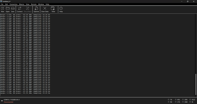
Here is the result (DW1000 modules placed at distance apart 0.2 meter):

So where is the error coming from? I don’t mean to sound unhelpful but I don’t have time to walk you through basic firmware debugging step by step.

Ignore the weird numbers at very short range. Once measured range goes negative you’re going to get odd things.

You move it and the distance changes. So which timestamps are changing? The remote ends delta time should remain constant (to within the tolerance of the scheduled transmits) is it?
This looks like a scale factor error of around 2 which would imply a maths problem in the code. The only odd bit is that numbers you’re getting aren’t linear. But when you are that close you can get all sorts of weird RF effects. Check whether it’s linear at a longer distance. If so then find the error in your maths, re-calibrate antenna delays and test again.

By mistake I shared wrong result. Here is the result I am talking about (DW1000 modules placed at distance apart 0.2 meter ):