DW1000 SFDLED Configuration

Hello!

I am developing a project based on STM32F4 + DWM 1000.

The system consists of one anchor and two tags:

  1. The Anchor performs TOF measurements for each Tag;
  2. The Anchor transmits an appropriate TOF measurements to each tag;
  3. The Anchor sends a synchro message to synchronize the local time of the Tags STM32;

TOF measurement and transmission works perfectly, but to synchronize the STM32 timers on the tag side, I want also use the SFDLED signal.

The problem is in follows: the DWM1000 SFDLED signals of both of my tags have a sufficiently large delay between them:


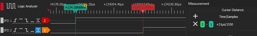
Although as I understand it, if the Tags are nearby, this signal should be generated simultaneously.

Tag and Anchor applications are based on dw1000_api_rev2p14_stsw API. Firmware for both tags is identical.

There is no SFDLED pin configuration function in the API, so I had to write it separately:

#define GPIO_PIN1_SFD         0x00000100UL    /* The pin operates as SFD LED output */

void dwt_setSFDgpio1(void)
{
    // Set GPIO Mode
    uint32 gpio_mode = dwt_read32bitoffsetreg(GPIO_CTRL_ID, GPIO_MODE_OFFSET);
    gpio_mode &= ~(GPIO_MSGP1_MASK);
    gpio_mode |= GPIO_PIN1_SFD;
    dwt_write32bitoffsetreg(GPIO_CTRL_ID, GPIO_MODE_OFFSET, gpio_mode);
    gpio_mode = dwt_read32bitoffsetreg(GPIO_CTRL_ID, GPIO_MODE_OFFSET);
    
    // Enable LP Oscillator to run from counter and turn on de-bounce clock.
    uint32 reg;
    reg = dwt_read32bitoffsetreg(PMSC_ID, PMSC_CTRL0_OFFSET);
    reg |= (PMSC_CTRL0_GPDCE | PMSC_CTRL0_KHZCLEN);
    dwt_write32bitoffsetreg(PMSC_ID, PMSC_CTRL0_OFFSET, reg);
    
    // Enable LEDs to blink and set default blink time.
    reg = PMSC_LEDC_BLNKEN | 0x01;
    dwt_write32bitoffsetreg(PMSC_ID, PMSC_LEDC_OFFSET, reg);
}

Initial DW1000 setup:

 
  static dwt_config_t config = {
    2,               /* Channel number. */
    DWT_PRF_64M,     /* Pulse repetition frequency. */
    DWT_PLEN_128,    /* Preamble length. Used in TX only. */
    DWT_PAC8,        /* Preamble acquisition chunk size. Used in RX only. */
    9,               /* TX preamble code. Used in TX only. */
    9,               /* RX preamble code. Used in RX only. */
    0,               /* 0 to use standard SFD, 1 to use non-standard SFD. */
    DWT_BR_6M8,      /* Data rate. */
    DWT_PHRMODE_STD, /* PHY header mode. */
    (129 + 8 - 8)    /* SFD timeout (preamble length + 1 + SFD length - PAC size). Used in RX only. */
  };
  
  static dwt_txconfig_t txconfig = {
    0xC2,            /* PG delay. */
    0x67676767,      /* TX power. */
  };

  reset_DW1000(); /* Target specific drive of RSTn line into DW1000 low for a period. */
  port_set_dw1000_slowrate();
  HAL_Delay(1000);
  if (dwt_initialise(DWT_LOADUCODE) == DWT_ERROR)
  {
    while (1)
      ;
  }
  port_set_dw1000_fastrate();
  dwt_configure(&config);
  dwt_configuretxrf(&txconfig);
  dwt_enablegpioclocks();
  dwt_setSFDgpio1();

Non-blocking RX handler (called as often as possible):

  case DWM_RX:
    if (handler->dwm.pocessing == 0)
    {
      dwt_rxenable(DWT_START_RX_IMMEDIATE);
      handler->dwm.pocessing = 1;
    }
    else
    {
      statusReg = dwt_read32bitreg(SYS_STATUS_ID);
      if (statusReg & SYS_STATUS_RXFCG)
      {
        uint16_t rxPacketSize = dwt_read32bitreg(RX_FINFO_ID) & RX_FINFO_RXFL_MASK_1023;
        if (rxPacketSize <= 0xFF + 4)
        {
          dwt_readrxdata((uint8_t *)&handler->rxPacketBuffer.packet, rxPacketSize - UWB_PROTOCOL_HW_CRC_LENGTH, 0);
          handler->rxPacketBuffer.rxTimestamp = dwt_readrxtimestamplo32() + (((uint64_t)dwt_readrxtimestamphi32() & 0xFF000000) << 8);
          Fifo_pushBack(handler->rxFifo, &handler->rxPacketBuffer);
          dwt_write32bitreg(SYS_STATUS_ID, SYS_STATUS_RXFCG | SYS_STATUS_ALL_RX_ERR);
          dwt_rxenable(DWT_START_RX_IMMEDIATE);
          break;
        }
        dwt_write32bitreg(SYS_STATUS_ID, SYS_STATUS_RXFCG | SYS_STATUS_ALL_RX_ERR);
        handler->dwm.pocessing = 0;
      }
      else if (statusReg & SYS_STATUS_ALL_RX_ERR)
      {
        dwt_write32bitreg(SYS_STATUS_ID, SYS_STATUS_ALL_RX_ERR);
        handler->dwm.pocessing = 0;
      }
    }

Do you send messages to 2 tags sequentially?
I.e. Msg to the first tag, then msg to the second tag?

Hello!

I send synchro message once for both tags.

I think, I figured out what was the root of my problem:

SFDLED GPIO functionality needs Kilohertz Clock to be enabled (PMSC_CTRL0_KHZCLEN in PMSC_CTRL0 Sub-register). Kilohertz Clock also controls GPIO De-Bounce clock timing.

  1. I lowered Kilohertz Clock Prescaler (Set KHZCLKDIV in PMSC_CTRL1 Sub-register to 0):

    reg = dwt_read32bitoffsetreg(PMSC_ID, PMSC_CTRL1_OFFSET);
    reg &= ~PMSC_CTRL1_KHZCLKDIV_MASK;
    reg += 0 << 26;
    dwt_write32bitoffsetreg(PMSC_ID, PMSC_CTRL1_OFFSET, reg);
    

    With this configuration SFDLED response difference reduced to ~10-40 ns but multiple SFDLED pulses on single packet receive appeared.

  2. Then I increased Blink time count value (Set BLINK_TIM in PMSC_LEDC Sub-register to 10 instead of 1):

    reg = PMSC_LEDC_BLNKEN | 0x0A;
    dwt_write32bitoffsetreg(PMSC_ID, PMSC_LEDC_OFFSET, reg);
    

    It solves multiple pulses problem, but 10-40 ns difference is still to large

  3. Then I tryed disable De-Bounce function for SFDLED GPIO instead of lowering Kilohertz Clock Prescaler:

    reg = dwt_read32bitoffsetreg(GPIO_CTRL_ID, GPIO_IDBE_OFFSET);
    gpio_mode &= ~(GIDBE1);
    dwt_write32bitoffsetreg(GPIO_CTRL_ID, GPIO_IDBE_OFFSET, reg);
    

    It had no effect.

Also when I disable De-Bounce clocking (GPDCE and GPDRN bits in PMSC_CTRL0 Sub-register) SFDLED stops working at all.

Is there a way to use SFDLED without De-Bounce function?

I think you’re going to hit a fundamental limitation of the part. The LED lines are intended to flash LEDs. They aren’t intended for accurate time indications, at least not that accurate.

Can I ask what you are doing that requires such accurate time synchronisation between the two anchors?
Unless you are also controlling for CPU clock speed differences no matter how accurately you synchronise them you’ll very quickly be that far out of sync again anyway.

1 Like

Hello!

The aim of my experiment is to generate an accurate synchronizing pulse on the STM32.

I assume that knowing the TOF in each tag, I can start a timer on both tags to compensate TOF and generate a pulse at the same time.

There are several articles on the Internet describing this mechanism. It is possible to achieve SFD detection accuracy with an accuracy of ~8 ns.

Keep in mind that on an M4 processor you’re going to have an interrupt latency of 12 clock cycles and a timing quantisation of 1 clock cycle. So at 180MHz you’ve got between 67 and 72ns of interrupt latency on the processor you’re using. Even if the UWB timing is perfect your processors are going to add 5 ns of variability.

My initial question is not about interrupt delays and clocking of STM32. I want to understand how to correctly disable the GPIO De-Bounce function.

Did you find a solution?

We are using the QM33110W (similar to DW3000 series), it would be nice if we had a way to timestamp packet reception separate from timestamping IRQ output. We presently set RXSFDD interrupt and timestamp that, and find it to be jittered by only +/- 4 ns due to internal 124.8 MHz clock, so quite accurate, but we’d like to avoid taking that interrupt just for that purpose.

The ideal would be if SFDLED could act as a timestamp output for packet reception, but without the LED blink delay stuff, just a brief pulse. Then that could feed into a timer capture and leave IRQ to do other tasks. Have you tried using SFDLED without BLINK_EN set? My hope would be this results in a very brief pulse aligned with the packet. The lowest BLINK_TIM value of 14 ms is completely unusable for timing packets.

Assuming SFDLED can’t be made to work as we hope, then none of the other “LED” signals are likely to work. There may be a few alternatives one could try that I can think of, all untested:

A. GPIO6 EXTSWRX

According to the documents, when GPIO6 is configured as EXTSWRX, the pin will go high at the start of the RX. This implies it goes low right at the end of a packet reception. One could timestamp on that falling edge to know exactly when the RF packet ended. Knowing the packet length, you can then mathematically adjust the time value to the SFD mark. Given a known set of RF parameters (PRF, bit rate), you could build a table of adjustment values index by packet byte length to make this quick in the code.

One possible bug with this idea is if you use RXAUTR (automatic RX reenable) and if that doesn’t briefly toggle EXTSWRX low and then high again right after a packet is received. If the RXAUTR does do the toggle, you are good (as long as the toggle time is recognized by your timer capture system). If there is no toggle of EXTRXSW, then this method fails if you use RXAUTR.

There is a little bit of timing skew that may be introduced between SFD point and the end of packet due to clock drift of the processor timer versus the UWB crystal. For a 10 ppm difference and a 500 us packet, that is 5 ns, so pretty much ignorable unless packet lengths are huge and clock skew is large.

B GPIO6 AOA_SW_2

If GPIO6 is configured to AOA_SW_2, then it toggles in the STS gap to allow an external RF mux to change antennas for PDAO measurements. That switch has to be precise relative to the packet. You could timestamp that switch.

This may not work is STS is not enabled, so it may be of limited usefulness.

C GPIO5 AOA_SW_1

This is similar to A option, but another pin. Don’t know if it toggles on RXAUTR or not.

D GPIO7 AOA_SW_3

Similar to B, with the same issues.

E. IRQ on RXSFDD or RXPHD

You can timestamp the IRQ for an interrupt that is time aligned with the packet. We know RXSFDD (SFD detected) works from past experience, but you usually don’t want to take that interrupt if you can help it. RXPHD (PHY header detect) would likely work, but same issue, and would require a fixed time adjustment back to the SFD point.

F. IRQ on RXFR

RXFR (frame ready) would seem like the interrupt you want but it lacks precise time relationship from the packet due to being delayed potentially by CIA_DONE. Note that RXFR can likely be made timing precise to packet if FAST_AAT is set (assuming that works even if AUTO_ACK is not set). But that still leaves you having to service the packet after CIA_DONE, RXFCG, RXFCE, a two step process.

This method would require adjustment of the time by packet length.

It seems odd to me that the UWB chips don’t provide a clear and easy output to timestamp packet reception. The SFDLED would be ideal if it could be used without the blink features. A 1 us pulse would be plenty.

Mike Ciholas, President, Ciholas, Inc
3700 Bell Road, Newburgh, IN 47630 USA
mikec@ciholas.com
+1 812 962 9408