DW1000 PCB Design - RF Transmission Line Length

Hello,

I have a general question regarding the RF transmission line length:

Is it generally desirable to make the RF transmission line as short as possible ?

My simple idea behind this question is that a short transmission line introduces less signal loss and of course less transmission delay.

Of course I am aware that the impedance has to match but this is done via the transmission line width anyway.

Long story short, should I try to make the transmission line as short as possible or are there other factors I need to consider ?

Best regards

Firstdragon

In general, yes, shorter is better.

There are, however, exceptions. Sometimes transmission lines of specific length are used for impedance matching purposes, or other effects.

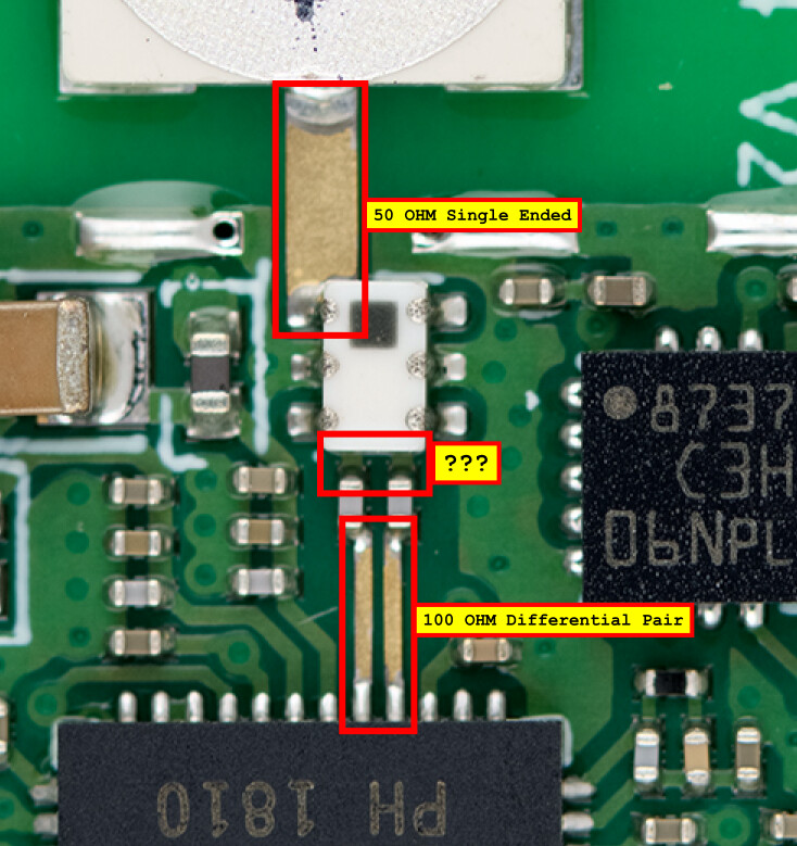
We’ve noticed that it is generally better, for any given distance between DW1000 and antenna, to run the differential pair longer and the single ended line shorter. That is, it is better for the balun to be near the antenna.

The DC block caps need to be ones rated for the frequency, not just generic caps, and not bigger than 0402.

Top side ground plane in the RF section needs to be poured liberally and have lots of vias to the the internal plane. Make sure the balun pins are well grounded.

The PCB material is important, maybe more so than the trace length. Generic FR4 is not so good at 6.5 GHz. There are a class of “slightly premium” PCB materials such as FR408HR, N4000-13, IT-200LK which cost only a little more but perform much better. The high end stuff, like Rogers, isn’t required, but junk FR4 is to be avoided.

Only true way to know what the design does is to make it and test it. At 6.5 GHz, RF is a bit of a black art and seemingly small things can have relatively big impacts.

Mike Ciholas, President, Ciholas, Inc
3700 Bell Road, Newburgh, IN 47630 USA
mikec@ciholas.com
+1 812 962 9408

1 Like

thank you. highly appreciated.

@mciholas

Hi,

sorry to bring this topic up again but an additional question came to my mind.

The official DW1000 data sheet recommends to implement the “middle” RF transmission lines as 50 ohm singled ended traces as shown below:

However, if I look at the following picture below, it is looks like the middle traces are not really implemented. It looks more like they do not really exist and the capacitor pads just go directly into the balun pads.

Are there any suggestions or experiences on this topic ? For example, what is better

1.) to implement the middle traces properly as 50 Ohm single ended or

2.) make them just as short as possible and let the capacitor pads directly go into the balun pad without caring about the width.