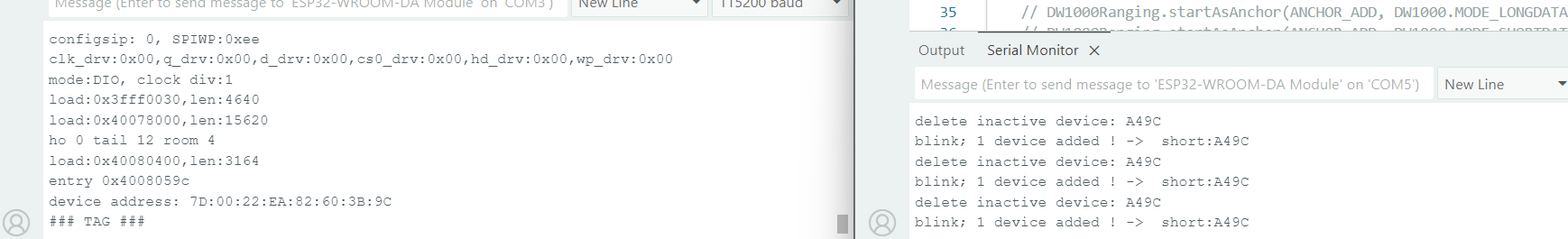
The step to read the device ID works successfully. But when it comes to distance measurement, the Tag MCU only shows the ID on the serial monitor, while the Anchor MCU displays output like the image below.
Sometime the tag print this
clk_drv:0x00,q_drv:0x00,d_drv:0x00,cs0_drv:0x00,hd_drv:0x00,wp_drv:0x00
mode:DIO, clock div:1
load:0x3fff0030,len:4640
load:0x40078000,len:15620
ho 0 tail 12 room 4
load:0x40080400,len:3164
entry 0x4008059c
E BOD: Brownout detector was triggered
Would indicate that the power supply you are using isn’t up to the job, the supply voltage is dropping too low.
Make sure you have good solid power connections to both the processor and the DW1000 module. Maybe add some capacitors as close as possible to the Vcc pins to help cope with the rapid changes in current draw that you get when turning radio transmitters on and off.
Thank you for your answer, but I would like to clarify further. This is the connection table between my ESP32 and DW1000 pins.
DW1000 pin
ESP32 pin
VCC (3.3V)
3V3
GND
GND
MOSI
GPIO 23
MISO
GPIO 19
SCK
GPIO 18
CSN
GPIO 5
RST
GPIO 27
IRQ
GPIO 34
You mentioned that the issue might be related to the power supply. I am currently powering the ESP32 through the USB port of my computer so that I can monitor the Serial output on the Arduino IDE.
So, do I need to provide a separate power supply for the DW1000, or is it enough to increase the input voltage for the ESP32? Right now, I find this board on the internet that can supply an input voltage of 6.5–16V to the ESP32. Would this solve the problem, or do I still need to power the DW1000 separately?
The log is implying that the ESP32 is browning out. That means the 3.3V supply on the processor is dropping.
Some very rough numbers, the ESP will be using 60-150mA depending on whether wifi is on or not. The UWB will be using about the same. So your worst case power draw is around 300mA. Basic USB spec is for a minimum of 250mA but most ports can supply more.
Seems unlikely to be an issue but possible. Using a different power source may help unless the issue is with the 3v3 regulator not being able to cope. Your system only has linear regulators so a higher voltage supply will only result in more heat, you need a supply with a higher maximum current.
If you have an oscilloscope handy then I’d say check the 3v3 voltage rail but I’m guessing that’s not an option.
If you add some large capacitors to the 3v3 rail this will reduce the voltage dips caused by sudden changes in current and so make the system more able to cope with short spikes of high current draw.
What I can’t see is the quality of the wiring and connections between the two boards, these should be as short as possible.
I am using jumper wires to connect the pins between the ESP32 and the DW1000, and the wire length is about 10 cm. Should I solder the wires to directly connect the two devices instead?
I’d start with the capacitors. Plugs vs soldered shouldn’t make much difference, it’s the inductance of the power source that matters.
I’ve not used the exact hardware you have, nor have I used the firmware setup you’ve got so I’m guessing based on the small amount of information you’ve given.
The brown out error may be a red herring and it could be a firmware configuration issue.