DW1000 and RP2040

I have two DW1000 UWB modules, and I want to use them as an Anchor and TAG. I am currently using the Arduino DW1000 library. However, I encountered an error during SPI initialization related to mbed OS. I would appreciate any assistance in resolving this issue.

I also attempted to port the Arduino DW1000 library to the pico C/C++ platform. Unfortunately, I only managed to obtain the Device ID, and I am struggling to establish communication between the two DW1000 modules. I kindly request your guidance in resolving this matter.

There was an old mbed DW1000 driver (from the mbed2 era). It doesn’t do any ranging but does handle configuring the device and gives you basic transmit / receive functions.

You need to give more detail and/or code if you want any real help. So far you’ve told us you have some code you wrote / joined together from multiple sources and it doesn’t work beyond reading address 0.
I’m not sure what to tell you other than you probably have a firmware bug and that the solution is to fix the firmware bug.

First, I used DW1000 Ardunio library that is by throto in which only Basic Connectivity example works. But, other examples such as DW1000Ranging_Anchor and DW1000Ranging_Tag example does not works. That means, module does not able to communicate with each other.

After that, I found stm32 firmware of DW1000 by Decawave. In this also I am just able to get device ID only, not able to establish communication between two DW1000 modules.

Note: In this stm32 firmware of DW1000 by Decawave, I ported SPI function according to RP2040 C/C++ SDK.

That doesn’t change much. Either you have a firmware error or you have a hardware problem.

There aren’t many hardware problems where you would get the correct device ID. Unless it’s something like the chip select line is wrong so only the first transaction works each power cycle it’s unlikely the issue is hardware.

So we are back to either you post the code or there isn’t much anyone can do to help.

I also attempted to test the Decawave DW1000 STM32 driver with the Nucleo-64 STM32FG070xx board, but I was unable to establish communication between the two DW1000 modules. Here is the STM32 project that I used. Link: stm32g070_test.rar - Google Drive

Hey Andy, if you can check that code. What is the error in it.

There is one more thing, when I try to read SYS_CFG register it gives “0xDEADDEAD” value. Why? Because this register is read writable.

Here is my RP2040 code to read from the DW1000 module and write to the DW1000 module.

#include “main.h”

DW1000 inst_DW1000;

TaskHandle_t irq_process_Handle = NULL;
void irq_process(void* args);

TaskHandle_t main_thread_Handle = NULL;
void main_thread(void* args);

int main()
{
stdio_init_all();
sleep_ms(1000);

gpio_init(25);
gpio_set_dir(25 , GPIO_OUT);

/* Configuring ADS1198 */
inst_DW1000.configure	= DW1000_configure;
inst_DW1000.configure(&inst_DW1000);

xTaskCreate(irq_process, "IRQ Process", 500, NULL, 2, &irq_process_Handle);
xTaskCreate(main_thread, "main thread", 1024, NULL, 2, &main_thread_Handle);
vTaskStartScheduler();

while (1)
{
    tight_loop_contents();
}


return 0;

}

void DW1000_configure(struct DW1000* instance)
{
// printf(“DW_Configure Run\r\n”);
/* SPI : GPIO , HOST and HOST Handler */
instance->spi._gpio.sclk_pin = DW_SCLK_Pin;
instance->spi._gpio.mosi_pin = DW_MOSI_Pin;
instance->spi._gpio.miso_pin = DW_MISO_Pin;
instance->spi._gpio.cs_pin = DW_CS_Pin;
instance->spi._gpio.irq_pin = DW_IRQ_Pin;
instance->spi._gpio.reset_pin = DW_RESET_Pin;
instance->spi.host = spi0;

/* Methods */
instance->IRQ_Callback  = DW1000_IRQ_Callback;
instance->readBytes     = DW1000_readBytes;
instance->writeBytes    = DW1000_writeBytes;

/* GPIO Init */
/* CS as OUTPUT */
gpio_init(instance->spi._gpio.cs_pin);
gpio_set_dir(instance->spi._gpio.cs_pin, GPIO_OUT);
sleep_ms(1);
/* IRQ as Input with Interrupt */
gpio_init(instance->spi._gpio.irq_pin);
gpio_pull_down(instance->spi._gpio.irq_pin);
gpio_set_dir(instance->spi._gpio.irq_pin, GPIO_IN);
gpio_set_irq_enabled_with_callback(instance->spi._gpio.irq_pin, GPIO_IRQ_EDGE_RISE, true, (gpio_irq_callback_t)instance->IRQ_Callback);

/*SPI initialization */
spi_init(instance->spi.host, 16*1000*1000);
spi_set_format(instance->spi.host, 8, SPI_CPOL_0, SPI_CPHA_1, SPI_MSB_FIRST);
// Initialize SPI pins
gpio_set_function(instance->spi._gpio.sclk_pin, GPIO_FUNC_SPI);
gpio_set_function(instance->spi._gpio.mosi_pin, GPIO_FUNC_SPI);
gpio_set_function(instance->spi._gpio.miso_pin, GPIO_FUNC_SPI);

sleep_ms(10);

}

void DW1000_IRQ_Callback(uint gpio, uint32_t events)
{
if(gpio == inst_DW1000.spi._gpio.irq_pin)
{
inst_DW1000.irq_flag_status = 1;
}
}

void irq_process(void* args)
{
while (1)
{
if(inst_DW1000.irq_flag_status == 1)
{
inst_DW1000.irq_flag_status = 0;
printf(“Hello\r\n”);
// do some process here
////////////////////////
}
vTaskDelay(10/ portTICK_PERIOD_MS);
}

}

void DW1000_readBytes(uint8_t cmd, uint16_t offset, uint8_t rxData[], uint16_t rxLen)
{
uint8_t header[3];
uint8_t headerLen = 1;
uint16_t i = 0;

// build SPI header
if (offset == 0xFF)
{
	header[0] = 0x00 | cmd;
}
else
{
	header[0] = 0x40 | cmd;
	if (offset < 128)
	{
		header[1] = (uint8_t)offset;
		headerLen++;
	}
	else
	{
		header[1] = 0x80 | (uint8_t)offset;
		header[2] = (uint8_t)(offset >> 7);
		headerLen += 2;
	}
}
gpio_put(inst_DW1000.spi._gpio.cs_pin, 0);						   // Set CS pin low to select the DWM1000 module
spi_write_blocking(inst_DW1000.spi.host, &header[0], headerLen); // Send the read command
spi_read_blocking(inst_DW1000.spi.host, 0x00, &rxData[0], rxLen);	   // Read the response
sleep_us(5);
gpio_put(inst_DW1000.spi._gpio.cs_pin, 1); // Set CS pin high to select the DWM1000 module

}

void main_thread(void* args)
{
uint8_t rxData[4];
while (1)
{
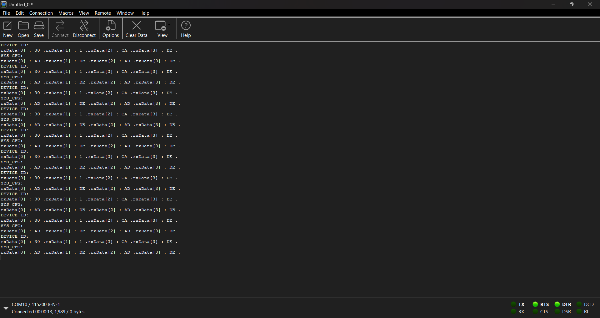
/* Read DEVICE ID register */
inst_DW1000.readBytes(0x00, 0xFF, rxData, 4);
printf(“DEVICE ID:\r\n”);
for(int i = 0 ; i < 4 ; i++)
{
printf(“rxData[%d] : %X \t”, i, rxData[i]);
}
printf(“\r\n”);

    sleep_ms(10);

    /* Read SYS_CFG register */
    printf("SYS_CFG:\r\n");
    inst_DW1000.readBytes(0x04, 0xFF, rxData, 4);
    for(int i = 0 ; i < 4 ; i++)
    {
        printf("rxData[%d] : %X \t", i, rxData[i]);
    }
    printf("\r\n");
    vTaskDelay(1000/portTICK_PERIOD_MS);
}

}

void DW1000_writeBytes(uint8_t cmd, uint16_t offset, uint8_t data[], uint16_t txLen)
{
uint8_t header[3];
uint8_t headerLen = 1;
uint16_t i = 0;

// TODO proper error handling: address out of bounds
// build SPI header
if (offset == 0xFF)
{
	header[0] = 0x80 | cmd;
}
else
{
	header[0] = 0xC0 | cmd;
	if (offset < 128)
	{
		header[1] = (uint8_t)offset;
		headerLen++;
	}
	else
	{
		header[1] = 0x80 | (uint8_t)offset;
		header[2] = (uint8_t)(offset >> 7);
		headerLen += 2;
	}
}

size_t sz = headerLen + txLen;
uint8_t txData[sz];
// Copy elements from header to txData
for (int i = 0; i < headerLen; i++)
{
	txData[i] = header[i];
}

// Copy elements from data to txData
for (int i = 0; i < txLen; i++)
{
	txData[headerLen + i] = data[i];
}

gpio_put(inst_DW1000.spi._gpio.cs_pin, 0); // Set CS pin low to select the DWM1000 module
spi_write_blocking(inst_DW1000.spi.host, &txData[0], sz); // send header and write values
sleep_us(5);
gpio_put(inst_DW1000.spi._gpio.cs_pin, 1); // Set CS pin high to select the DWM1000 module

}

Please check the result of that:

At first glance you look to be running the SPI bus at 16 MHz all the time.
The maximum is 3MHz until the PLL is locked. Also you need to make sure your hardware is good for that speed, assuming reasonable quality connections that should be fine but I’ve seen SPI fall over at far lower speeds on some breadboarded systems.

Is your SPI mode set correctly? This will depend on the power up state of pins 9 and 10 on the module. You are setting a non-standard mode so I am assuming you have some pullups / downs on those pins to set the mode.

Now, I am able to read and write via spi at 16MHz spi clock. But, After a soft-reset, I am unable to read the register correctly as it gives me incorrect values, such as 0xFFFFF.

Here is my DW1000 initialize method:

int DW1000_Init(struct DW1000 *instance, uint16_t config)
{
uint16_t otp_addr = 0;
uint32_t ldo_tune = 0;

pdw1000local->dblbuffon = 0; // Double buffer mode off by default
pdw1000local->wait4resp = 0;
pdw1000local->sleep_mode = 0;

pdw1000local->cbTxDone = NULL;
pdw1000local->cbRxOk = NULL;
pdw1000local->cbRxTo = NULL;
pdw1000local->cbRxErr = NULL;

uint32 ID = instance->readdevid(instance);

printf("ID : %X\r\n", ID);
sleep_ms(10);

/* Read and validate device ID return -1 if not recognised */
if (DWT_DEVICE_ID != ID) // MP IC ONLY (i.e. DW1000) FOR THIS CODE
{
    return DWT_ERROR ;
}

/* Make sure the device is completely reset before starting initialisation */
instance->softreset(instance);

instance->enableclocks(instance, FORCE_SYS_XTI); // NOTE: set system clock to XTI - this is necessary to make sure the values read by _dwt_otpread are reliable

// Configure the CPLL lock detect
instance->write8bitoffsetreg(instance, EXT_SYNC_ID, EC_CTRL_OFFSET, EC_CTRL_PLLLCK);

// Read OTP revision number
otp_addr = instance->otpread(instance, XTRIM_ADDRESS) & 0xffff;        // Read 32 bit value, XTAL trim val is in low octet-0 (5 bits)
pdw1000local->otprev = (otp_addr >> 8) & 0xff;            // OTP revision is next byte

// Load LDO tune from OTP and kick it if there is a value actually programmed.
ldo_tune = instance->otpread(instance, LDOTUNE_ADDRESS);
if((ldo_tune & 0xFF) != 0)
{
    // Kick LDO tune
    instance->write8bitoffsetreg(instance, OTP_IF_ID, OTP_SF, OTP_SF_LDO_KICK); // Set load LDE kick bit
    pdw1000local->sleep_mode |= AON_WCFG_ONW_LLDO; // LDO tune must be kicked at wake-up
}

// Load Part and Lot ID from OTP
pdw1000local->partID = instance->otpread(instance, PARTID_ADDRESS);
pdw1000local->lotID  = instance->otpread(instance, LOTID_ADDRESS);

// XTAL trim value is set in OTP for DW1000 module and EVK/TREK boards but that might not be the case in a custom design
pdw1000local->init_xtrim = otp_addr & 0x1F;
if (!pdw1000local->init_xtrim) // A value of 0 means that the crystal has not been trimmed
{
    pdw1000local->init_xtrim = FS_XTALT_MIDRANGE ; // Set to mid-range if no calibration value inside
}

// Configure XTAL trim
instance->setxtaltrim(instance, pdw1000local->init_xtrim);

// Load leading edge detect code
if(config & DWT_LOADUCODE)
{
    instance->loaducodefromrom(instance);
    pdw1000local->sleep_mode |= AON_WCFG_ONW_LLDE; // microcode must be loaded at wake-up
}
else // Should disable the LDERUN enable bit in 0x36, 0x4
{
    uint16 rega = instance->read16bitoffsetreg(instance, PMSC_ID, PMSC_CTRL1_OFFSET+1) ;
    rega &= 0xFDFF ; // Clear LDERUN bit
    instance->write16bitoffsetreg(instance, PMSC_ID, PMSC_CTRL1_OFFSET+1, rega) ;
}

instance->enableclocks(instance, ENABLE_ALL_SEQ); // Enable clocks for sequencing

// The 3 bits in AON CFG1 register must be cleared to ensure proper operation of the DW1000 in DEEPSLEEP mode.
instance->write8bitoffsetreg(instance, AON_ID, AON_CFG1_OFFSET, 0x00);

// Read system register / store local copy
pdw1000local->sysCFGreg = dwt_read32bitreg(instance, SYS_CFG_ID) ; // Read sysconfig register

return DWT_SUCCESS;

}