I am designing a custom PCB using the DW1000 and an STM32 MCU. In the reference designs and datasheet for the DW1000 there is usually a 1.8V switching regulator to provide 1.8V to VDDLDOA and VDDLDOD. This is done to help with power consumption on battery powered devices however my design will be powered by USB so I’m less concerned with power consumption. The datasheet says the 1.8V external switching regulator is optional and that the DW1000 has internal 1.8V LDOs.
Can I simply provide 3.3V to all supply pins on the DW1000 including VDDLDOA and VDDLDOD?
Also if I’m not using the 1.8V external regulator then I have no need to use the EXTON pin to control the ENABLE of the regulator. Can I tie the EXTON pin to GND?
EXTON is an output, I wouldn’t recommend tieing an output to a power rail. It should be fine to just leave it no connect.
You can just feed 3.3 vin to the power inputs. The internal LDOs are to around 1.3-1.4 V, the 1.8V is to give them enough headroom to operate while minimising the amount of power they have to dissipate.
Personally if power consumption isn’t an issue and I had the board space I’d use an external LDO to 1.8V. When RX is enabled if you feed in 3.3V those internal LDOs will be dropping an extra 1/3 of a watt. For long term reliability I’d rather put that extra heat external to the radio chip if I can.
First of all, I do not know whether my answer should be a separate thread or not, sorry for that. Anyway, I am wondering what is the absolute lowest voltage to supply to said 1.8 V pins ?. Assuming that there are internal LDOs after some minimal margin for headroom, the rest of voltage just goes to heat. For instance using the most simplistic LDO efficiency formula (Vout/Vin) moving from 1.8 V to 1.6 V would provide about 10 % efficiency gain. Is the 1.6 V enough for LDOs headroom ? We tried the 1.6 V on one of our devices and it worked quite well and weirdly the RF output specter of the device seemed to improve. It might be one off lucky chance though. That being said, our 1.6 V DC/DC was quite heavily filtered and had large input and output capacitors.
The datasheet does give minimum allowable input voltages on VDDLDOA & VDDLDOD as being 1.6V.
So setting your power input to a nominal voltage of 1.6 V seems like a bad idea. It may well work most of the time. But designing for most of the time is a very bad habit to get into. You don’t want something that falls over on some parts or at certain temperatures or workloads.
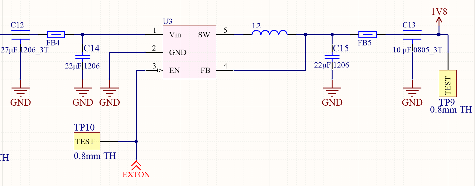
Once you factor in power supply tolerance over the full operating range and things like DC losses in FB5 when at peak current (looks like that’s 210mA) you’ll probably have to run with a nominal supply voltage close enough to 1.8 V that it’s not worth the effort.