Is it possible to modify built-in symbols of native devices? Where are they located?
Possibly, if you find a symbol in the “Symbols & IP Browser” opened with [F2], and right click on the symbol, the local-menu entry “Open a Copy & Edit” will give you what you want.
One more trick
- Place the device in schematic (can be native or behavioral or from someone library)
- Hover mouse cursor over the device, Copy it with Ctrl-C
- File > New > New Symbol
- In Symbol window, Ctrl-V to paste it
Now, you can modify the device and save as a new symbol.
I shared some of my modified devices in my Symbol library may give you more idea how you possible to play with the device modification
Qspice/Symbols/qspice-alternative at main · KSKelvin-Github/Qspice
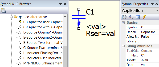
You are not limited to only modify its outlook, but for example, this is a build-in capacitor with instance parameter Rser included, and it can look like a symbol for a capacitor with ESR, and save you a few click in adding attribute Rser.

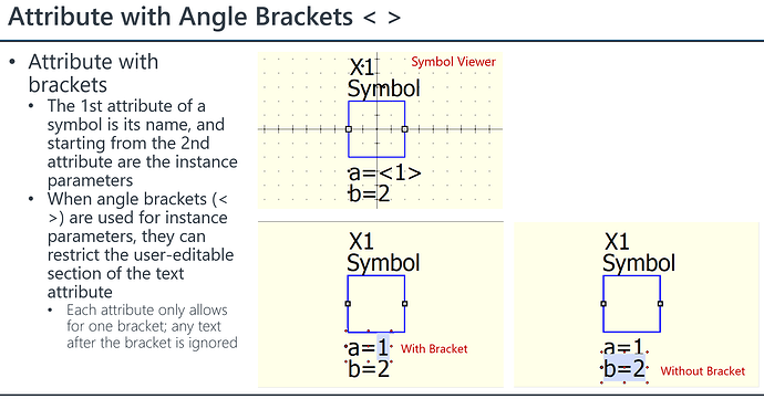
Here is how to use angle brackets <>. Knowing this will help you to build a better symbol.
They are all embedded in the code and all keyboard shortcuts, etc., are hardwired. So currently no possibility for any configuration changes except for creating own symbols, as mentioned above.
@mgyger has well catched the point … the topic in object is about a change of the built-in symbols and not how to create new ones from what is already in the native devices list. Sometime, in fact, this list results not embracing all the effective needs (for example, the case of intrinsic body diodes for MOSFETs, etc).
We must understand what we are asking before we ask.
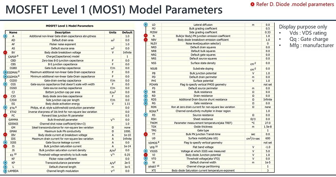
For example, the intrinsic body diode of MOSFETs is in the MOS model. An example is the level 1 MOS1 model with model parameters highlighted in red, which are used to model the bode diode. Qspice supports MOS1, MOS2, MOS3, BSIM1, BSIM2, BSIM3v3.3.2, BSIM4v4.8.1 and modified EKV v2.6 according to its help.
The question you are posing relates to the capability of defining your own equation. In some cases, manufacturers achieve this by using a B-source to establish their custom equation (for example, use sub-circuit to model a MOSFET). However, the ability to modify the equations of native devices can only be accomplished by writing your own SPICE program.
I know exactly what I’m asking ![]()
The topic, in fact, is about a symbol and not its model. In the specific case of the example is more an aesthetical point than a functional one …
Oh… I misunderstood your second reply. You are still referring to changing the symbol to match the view you need. I went through that message too quickly and misunderstood that you wanted to modify the device equation. I apologize; English is my second language, and sometimes I can make simple mistakes. ![]()
While it’s technically possible to modify built-in symbols on native devices, it’s generally not recommended and can lead to serious consequences.
Fully agreed with you that developers should pay attention with these kind of changes … but disabling the editing option for some of the built-in symbol properties of native devices, like for example “pin nets” and symbol “type”, may be the right way to go …

