I have started playing around with coupled inductor simulations and the transformer model recently. But I ran into problems during transient simulations.
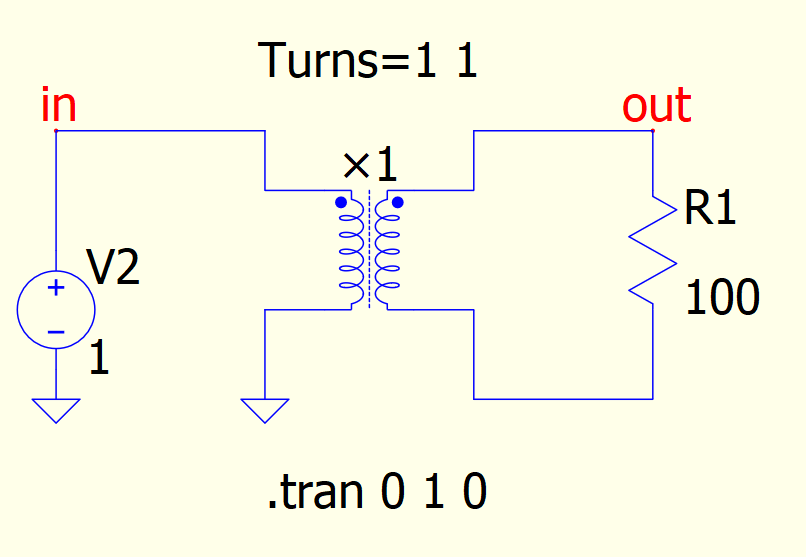
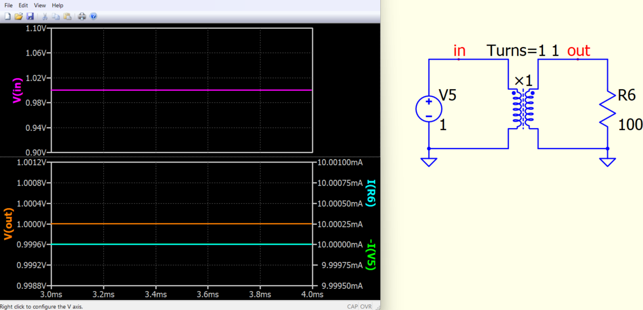
Here you can see a simulation I tested after I first recognized the problem with ordinary coupled inductors. The voltage source is set to constant 1V.
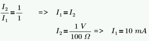
I would expect the output to be 0V since DC currents should not lead to any changing magnetic field and therefore not to any induced current on the load side. But i can measure constant 1V over the load resistor and the corresponding 10mA DC through it. Even with the ‘.op’ simulation type.
Maybe I am missing something obvious here. It would be nice if someone could point it out for me then, as i am unable to find anythind about this behavior online.
Your expectation is to have a 0V output in secondary of the circuit. However, this expectation is based on the assumption that in DC steady state, the inductor acts as a short circuit. And therefore, the voltage across the primary is 0V, resulting in 0V coupled to secondary.
However, as you force a 1V DC voltage source without series resistance and with an infinite L (×-Device in default set L to infinite), above assumption no longer holds. By XL = 2*pi*f*L, now f=0 but L=inf, the inductor impedance at DC becomes undefined. Additionally, voltage source without a series resistor forces primary voltage must be 1V.
In short, this setup is not reasonable, and it is not expected to yield any meaningful or reasonable results.
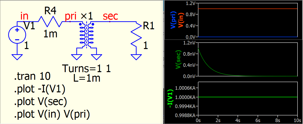
Here is a setup that includes a 1mΩ resistor in series and a primary inductance of 1mH. Generally, this is not a practical circuit to build, as it would result in a source current of 1kA for the DC solution (1V/1mΩ = 1kA). However, this demonstrate how to obtain a 0V primary voltage using the ×-Device or coupled inductors with a DC source connected to primary.
Anyway, just make sure to block any DC into a transformer.
By the way, I have a feeling that the ×-Device may behave mathematically as a DC transformer (not physically exist) if the inductance value is not specified. The results obtained from such a setup appear to be similar to E-source with Gain=1.
When constructing transformers, an ideal transformer is used, which also works on direct current. It becomes non-ideal when adding inductance in parallel to the input winding of an ideal transformer. For example, transformers are made in this way in the Multisim program. When I made models of nonlinear and linear transformers for LTspice, I made an ideal transformer (though it consisted of windings). QSPICE also has an ideal transformer, and this is good. This transformer can be used to model a gear mechanical transmission.
Of course it is not a reasonable setup. I started to observe this behavior while experimenting with the model itself. I can not prevent dc current to go into the transformer in my actual application. But it is low enough to not saturate the core or be a problem otherwise.
I think I just forgot for the moment, that the SPICE inductor is just a model element and not a real coil as long as i dont specify the parasitics accordingly.
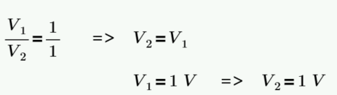
When most people learn transformer, they start from ideal transformer, which represent V2/V1=N2/N1. But textbook normally doesn’t remind you is that, physical transformer in electronics is always magnetic couple, which form by coupled inductors. The ideal transformer assume magnizating inductance (parallel to primary) is infinite and therfore be ignored as it gives infinite impedance in ac analysis at any frequency.
But for example, you work on power electronics or higher frequency, inductance of a transform becomes a MUST, as current is expected to flow through magnizating inductance, and unlike ideal case that inductance impedance is infinite that current flow is 0A and can be ignored.
This is reason why @bordodynov mentioned the ideal transformer, the math still valid in DC, as ideal tranaformer is a math model which modeling the equation V2/V1=N2/N1=I1/I2. But physically as @BEEbUCKET expectation that how come a transformer can couple DC as DC should short to ground in primary. This is all because ideal transformer alone cannot model a physical transformer.
Prof. Sam Ben-Yaakov has many video talks about transformer, this may be one that can help.
One more, as @bordodynov mentioned, Qspice offers ideal transformer (i.e. ×-Device with default parameters). It remind me that LTspice does not offer that. LTspice users normally come with a question how to model a transformer and learn about coupled inductors model. So, we can expect question in Qspice may be why transformer not work as expected in power electronics circuit for beginner, if they just take a ×-Device in default.