Custom TDoA System with DWM1004C tags and DWM1001+RasPi Anchors

Hi Everyone,
I am working on building a relatively small scale for cheap sports tracking. I am looking to start at an MVP of 3-4 anchors with 10 tags and then, if successful, scaling to a maximum of 8-10 anchors with 100 tags.

My plan is the use he DWM1004C for tags and DWM1001 (from the MDEK) + RaspPi for Anchors.

In terms of designing the system, there seem to be 2 big complexities by doing TDoA: Time Sync and backhaul.

Time Sync:

  • DW1001 will receive pulses, convert to tag signature and digitally pass to raspPi for timestamping.
  • RaspPi will be equipped with RTC/TCXO module
  • Time sync messages will happen over UWB waves.
  • Aiming for <5ns precision

Backhaul:

  • Most systems seem to use Ethernet for backhaul but I find this prohibitive for many outdoor settings
  • Our most-expensive case backhaul would be (100 tags)(10 pulses/second/tag)(100bits/pulse)*(10 anchors) = 1Mbps received by the server.
  • This should be achievable via Wifi/BLE5 in the raspPi

We plan to write all the multilateration and time sync algos ourselves.

Does anyone have any feedback or problems they see with this design? I am most worried about Time Sync since that is what seems to be the prohibitive part about TDoA systems.
3 Likes

I couldn’t see how this “precise” TCXO module can help doing TDoA time sync. DS3231 is okay to build a watch but is useless in your system - you need to provide DW1000 with main 38.4MHz clock as accurate as possible.
How are you going to use the RTC module to do the time sync?

Yeah I was wrong. I was hoping the TCXO on the RTC module for the RaspPi would be accessible and we could use it.

I am looking into ways to have the TCXO read into a RaspPi. I am also wondering if the clock on the RaspPi itself would work by itself. Do you know?

Also, I have seen some people struggle at getting the TCXO 38.4GHz clock into a DW1000.

I would suggest you test the devices you have in mind for range and see if they have adequate coverage of the playing field when operated at regulatory limits.

Also, TDoA requires a minimum of 4 anchors receiving one tag to produce a location. Your MVP of 3 to 4 won’t work at 3 and will be marginal at 4.

That’s inadequate for TDoA style systems since it represents 1.5 meters of time uncertainty in the anchor messages. That means a system with 1.5 meters of location error to each anchor and location outputs that will be a mess.

You need to time sync (or more precisely time model) anchors to 50 ps or less. This is very much not trivial, particularly in a sports environment where anchors may not be able to hear UWB messages from each other across a field. This is really challenging for a large sports field, like cricket, baseball, football (both kinds), etc.

Possibly, but beware that when an anchor is transmitting Wifi/BT, it may deafen the UWB to reception of tag beacons just from RF input saturation. Careful RF design will be necessary to allow an anchor to both receive a tag and transmit a Wifi/BT message at the same time. Or, you have to time slice the two systems, alterante UWB and BT/WIfi, which is complex as well. Or you can backhaul over UWB, which limits system capacity severely and can have range problems. Lots of tradeoffs to consider here.

It will take man years to do that, good luck. UWB location code is something that looks simple from the outside due to idealistic ideas of what it takes, but is messy and complex to do it with any real success once you get into it with any depth. We’ve invested 75 man years of effort to get our system where it is. There are lots of parts to it: location algorithm, output filtering, time sync algorithm and method, sensor integration, firmware, air time scheduler, backhaul system, system provisioning, user interface, graphical display, and so forth.

UWB location code is like computer vision algorithms. Simple in principle, very complex in practice if you want them to work well.

Mike Ciholas, President, Ciholas, Inc
3700 Bell Road, Newburgh, IN 47630 USA
mikec@ciholas.com
+1 812 962 9408

1 Like

I agree to get to a final product level, there is an insane amount of work.

That said, I still feel that one of the only limiting factors to make a small scale MVP (basketball court) is the time sync. Everything else seem to be problems with scale for the most part.

And with time sync, I essentially am struggling to find enough information to guarantee what will work and what won’t. So I guess I am going to go about trying a few different things.

You can’t separate sync and scale issues, they are tied together.

The simplest form of time sync is a single master node, in a fixed location, that beacons periodically to the set of anchors. You subtract the time of flight for the master packet to reach each anchor (you have to know the location of the anchors and master to do this). This gets you a stream of (master, slave) time pairs at each node. When a tag hits an anchor, you interpolate the tag arrival time between the master packets to put them into the master time frame. Now everything in the network is in one time and you can compare time of arrival at each anchor.

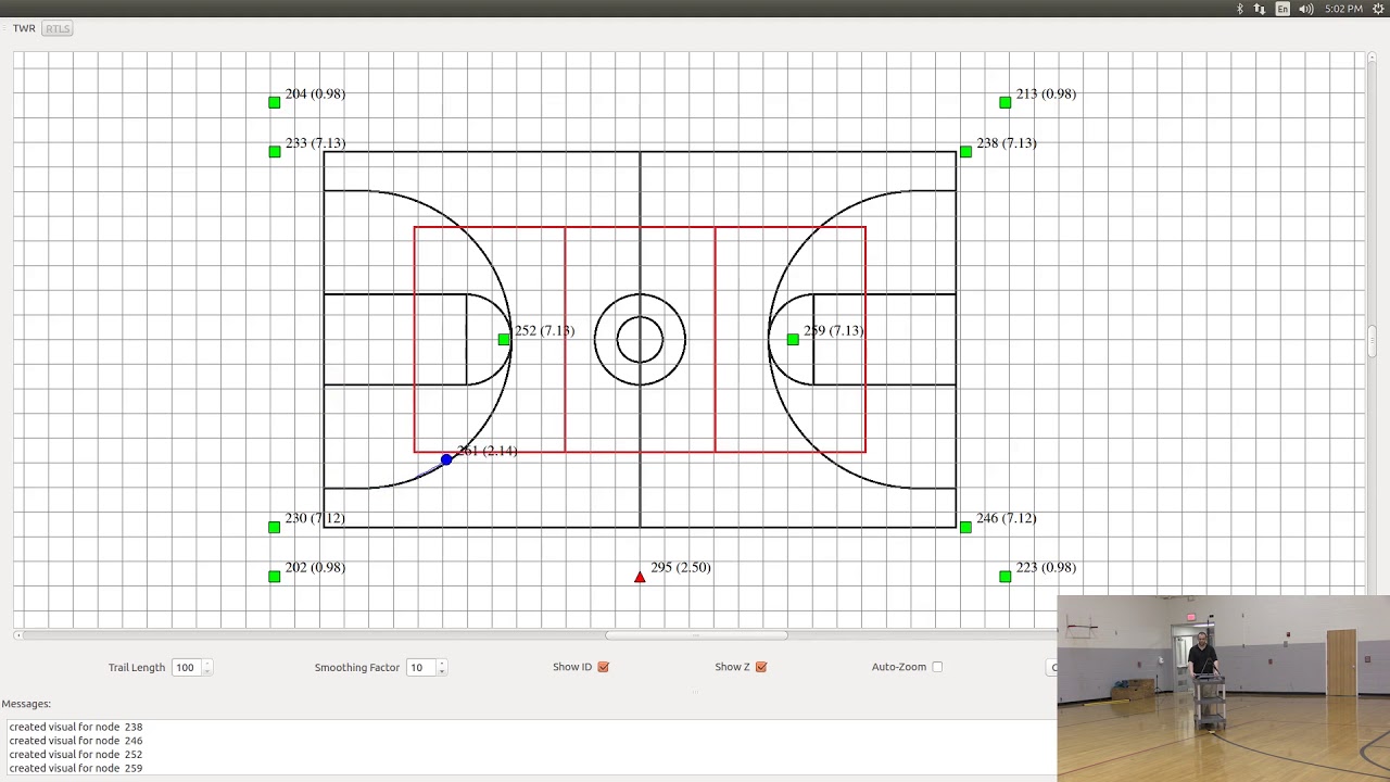
Here’s an example of this method at work that we did 5 years ago using our early DWUSB devices:

The master is the red triangle center bottom of the picture. It cannot participate in the location solution since it cannot correct for its own antenna delay. The slave anchors are green squares, 10 in total (6 on ceiling, 4 on floor tripods, temporary setup). The blue circle is the tag. The numbers are node serial numbers and the height in Z axis is in parens (). You can see which anchors are on the ceiling and which are on the floor by the Z axis heights. All units are in meters, and the background grid is 1 meter spacing.

The main limitations are that you can’t have anchors which can’t hear the master, so that limits your network size. Another limitation is that the timing noise is a combination of the master noise and the tag noise due to the simple interpolation method.

We long ago abandoned this method for a more sophisticated distributed sync system that can synchronize multitudes of anchors spread over a wide area. This method also models the TCXOs in the anchors to mostly eliminate the reference time noise leaving the tag time noise as the dominant uncertainty in the system. The development of this technique took several man years, and we continue to improve and revise it to this day. The system enables the ability to install anchors in a 100,000 m^2 (1,000,000 square foot) warehouse and have a seamless uniform sync of time all over the building.

Converting time to position is not a trivial task. Good luck!

Mike Ciholas, President, Ciholas, Inc
3700 Bell Road, Newburgh, IN 47630 USA
mikec@ciholas.com
+1 812 962 9408

3 Likes

As mciholas indicated the simplest method to get sync is to have a static tag at a known location.

It can then send out a pulse at a fixed interval. Each anchor can listen to that tag and use its reception minus the time of flight time (which is known since the location is known) to give a time synchronization mark that is common to all anchors. By measuring the period between these markers on each anchor you can then calculate the differences in the 38.4 MHz clocks on each anchor and so compensate for those errors.
For larger areas you can use multiple static tags, as long as they have some overlap so that the same anchor can see both then you can calculate a common synchronization zone.
Ideally you’d then smooth the calculated synchronization point and clock rates for each anchor using something like a kalman filter in order to allow for measurement noise but for a first pass a low pass filter and some linear interpolation will be close enough.

Don’t be put off by his 75 man years of work number. Getting to the point of a robust polished product and getting that last bit of accuracy can take a very long time but a basic proof of concept type system is a lot quicker.
I managed to get a basic position calculation system (admittedly post processing the final solution in python on a PC) up and running from scratch in a couple of months. Refining that and improving the firmware and hardware to go from the 30 cm accuracy it initially gave to the couple of cm accuracy we now have then took over a year. And after that the best part of a year with several people working on it to take that prototype system and turn it into a real product that could be sold.

So yes, getting a high accuracy system to the point where it’s marketable represents a reasonable number of man years of work. But a basic proof of concept is a very different matter. I’m not going to claim it’s quick or easy but it is possible in a reasonable time frame.

1 Like

Thank you so much for you response.

Our goal for 2-3 months is just to get a rough prototype working. 30cm is the exact level of accuracy we are aiming for right now.

When you say “38.4MHz clock” you are referring to the oscillator on a TCXO, right? I assume this is used with a PLL to get nanosecond level readings but I am wondering why a GHz speed clock (as the one in a RaspPi 4) can’t just be used? If I sync with pulses every, say, 100ms why would that be significantly worse? Is the drift on a RaspPi clock that much worse than that of a TCXO?

Were these filter recommendations in regards to processing the raw signal out of the oscillator?

Again thanks so much for the help! Our team is relatively light in terms of experienced hardware experts.

It is more complex than that. The 38.4 MHz clock (which can be a crystal, a TCXO, or an external clock source) feeds a PLL that multiplies it by 13 to get 499.2 MHz. This is divided by 4 to get 124.8 MHz which runs much of the internal circuitry on the DW1000. The 499.2 MHz also serves as the basis for the carrier PLL, for example, channel 5 is 499.2 MHz multiplied by 13, 6.4896 GHz.

The accumulator appears to work on a 998.4 MHz clock (roughly 1 ns per sample). Timing to 15.65 picoseconds is done by the LDE algorithm and there is no actual 64 GHz clock.

Transmit state machine appears to work on the 124.8 MHz clock, hence the 512 transmit time quantization (TX launch times are on 512 tick boundaries).

There is no access to that clock, it is internal to the processor of the RaspPi 4. You can’t timestamp an external signal with it, and you can’t pin it out to use it by external circuits. It is simply too fast to exist anywhere other than internal to the processor itself.

This is also true of the DW1000. That is why it has a 38.4 MHz reference clock and then makes all the other much higher frequencies from it.

Describe how you “sync with pulses”. As you attempt to do that, I think you will uncover you’ve made assumptions about the circuits and features that will turn out to be false. The circuits simply can’t do what you want them to do.

In the UWB system, the most critical clocks are the 38.4 MHz clocks fed into the DW1000. How stable and accurate those are determine a lot of the performance of the system. What the processor clocks are is mostly irrelevant since those are not involved in the precise timing of UWB packets.

Most assuredly. The RaspPi uses an ordinary crystal which will be affected by temperature and have an initial tolerance much worse than the TCXO.

Mike Ciholas, President, Ciholas, Inc
3700 Bell Road, Newburgh, IN 47630 USA
mikec@ciholas.com
+1 812 962 9408

Do you have any references on how to effectively use a Kalman filter in a TDoA like project?

No, sorry. That’s not how our system works right now, it’s just on my list of things to look into when I get time.

Yeah actually we figured it out. Kalman filtering isn’t actually necessarily the hard part. What I am struggling with is picking an approach to do the localization math.

We found so many papers with Maximum Likelihood estimators, Hyperbolic least squares, gauss-newton approximators, etc. And it’s hard to get a good gauge at which approach might be best for the errors in our data…

It depends on what sort of response you want out of your position calculation.

Rather than coming at it from scratch look at GPS as a reference, after all they are doing much the same thing and have spend decades trying to come up with the best way to solve this problem. And by look at GPS I mean look at what the actual GPS companies did rather than what academic research papers were saying. That’s a good way to filter out methods that on paper are better but in practice either are too complex, too fragile or simply not worth the effort for the extra benefit.

Until very recently all the high end GPS companies used either a least squares or a weighted least squares position calculation method for basic GPS. Just a basic linear least squares works well, after all GPS had to run on 1970’s era computers. Now most systems have also implemented a kalman filtered position calculation method however they still have a least squares mode that the user can set the system into. Why both? Because while Kalman filtering does give a smoother and cleaner position it also results in a recovery time after a position error while a least squares will jump directly back once the measurement error is gone.

Ironically the lower end consumer GPS is more likely to use a kalman filter than the high end systems, their market wants to see nice smooth data that doesn’t have sudden jumps when you plot it. The high end market on the other hand would rather get a best guess for this instant regardless of the history and then apply any filtering/smoothing at an application level.

So what’s the best position calculation method? Depends on what you are trying to do and what you expect the noise sources to be but I’d say the best option is to try the most basic solution first and see if that does what you need. It’ll certainly give you a good estimate of how good your system is working and if it’s good enough then why over complicate things?

Hi, just wanted to share our video report of our product and findings!! COVID did cause a major shift in our project but your responses played a HUGE part in the decisions we made and our success.

Thanks so much!

2 Likes

Nice work. Well done.