Coordinate Calculation in Downlink TDOA UWB Positioning System
For UWB positioning systems, there are multiple positioning technologies such as TWR (TOF), TDOA, PDOA, and also systems that combine multiple technologies.
TWR is the full name for Two-Way Ranging. By measuring the distance from the Tag to several Anchors and using a trilateration algorithm, the Tag’s coordinates are calculated. TWR technology is sometimes referred to as TOF technology. TWR technology is further divided into DSTWR (Double Side TWR) and SSTWR (Single Side TWR). Since TWR is relatively easy to implement, with even Decawave providing numerous code examples in their chip routines, it is easy to get started.
PDOA is the full name for Phase Difference of Arrival. Typically, an Anchor will have two or more antennas. When a signal emitted by the Tag arrives at the Anchor, the angle of the Tag’s position relative to the two Anchor antennas causes one antenna to receive the signal slightly earlier than the other. The chip usually uses the phase difference of the signal to calculate this time difference, which can determine the Tag’s direction from the Anchor. When there are multiple Anchors, the intersection of the direction lines measured by each Anchor is the Tag’s coordinate. Sometimes, this can be combined with TWR technology; once an Anchor measures the Tag’s angle and distance, the Tag’s coordinates can be determined, achieving a single-Anchor positioning effect.
TDOA is the full name for Time Difference of Arrival. Because the distance from the Tag to each Anchor is different, when the signal emitted by the Tag arrives at any two Anchors, the closer Anchor will receive the signal first, and the farther one will receive it later. The time difference in receiving the signal between two Anchors results in a hyperbola (hyperboloid), and the Tag’s position lies on this hyperbola. With multiple Anchors, we get multiple hyperbolas, and the intersection of these hyperbolas is the Tag’s coordinate.
TDOA is divided into two schemes: Uplink and Downlink. In the Uplink TDOA scheme, the Tag transmits a positioning signal, and the various Anchors receive the signal from the Tag, recording the timestamp of reception. This data is sent to a server, where a Real-Time Location Engine (RTLE) software calculates the Tag’s coordinates. In the Downlink TDOA scheme, the various Anchors transmit signals, and the Tag receives these signals, recording the timestamps of reception. By comparing these timestamps, the Tag calculates its own coordinates or forwards the data to an RTLE for calculation.
You might have noticed that the working mode of the Downlink TDOA scheme is very similar to GPS. GPS deploys many satellites in the global sky, and these satellites continuously emit positioning signals. When a GPS receiver receives the positioning signals from these satellites, it records the timestamps of reception. By comparing these timestamps, the receiver calculates its own coordinates.
For Downlink TDOA, multi-level clock synchronization is a very important technology. In previous articles, I have introduced the clock synchronization for Downlink TDOA. Recently, I spent some time researching the coordinate calculation for Downlink TDOA.
When the Tag receives enough positioning data packets from Anchors, such as receiving data packets from 3 Anchors, the condition for calculating 2D coordinates is met. The coordinate calculation for Downlink TDOA can be done directly by the Tag, or the Tag can send the data to a server where an RTLE (Real-Time Location Engine) performs the calculation. Both methods have their pros and cons.
-
Tag-side coordinate calculation. The advantage is that it does not rely on an additional server, similar to a GPS terminal. After the Tag calculates the coordinates, applications like navigation can be implemented. The disadvantage is that the Tag requires sufficient resources (MCU computational power, memory, etc.). Even if the application system requires a server, a less expensive one can be used. However, if an RTLE calculates the coordinates for all Tags, the resource requirement is very high, needing a high-performance server, or even a cluster of servers if the number of Tags is large. Tag-side calculation can save on the hardware costs of the RTLE.
-
RTLE-side coordinate calculation. The advantage is the reduced requirements for the Tag, which only needs to simply forward the received positioning data packets to the server, and the rest of the work is done by the RTLE on the server. The disadvantage is the need for a separate server, which increases system costs.
In my previous Uplink TDOA positioning system, I used an RTLE to calculate the Tag’s coordinates. For this Downlink TDOA system research, I decided to calculate the coordinates on the Tag side. Of course, when it is launched as a product, there will certainly be diverse modes, including products with Tag-side calculation and those with centralized RTLE-side calculation.
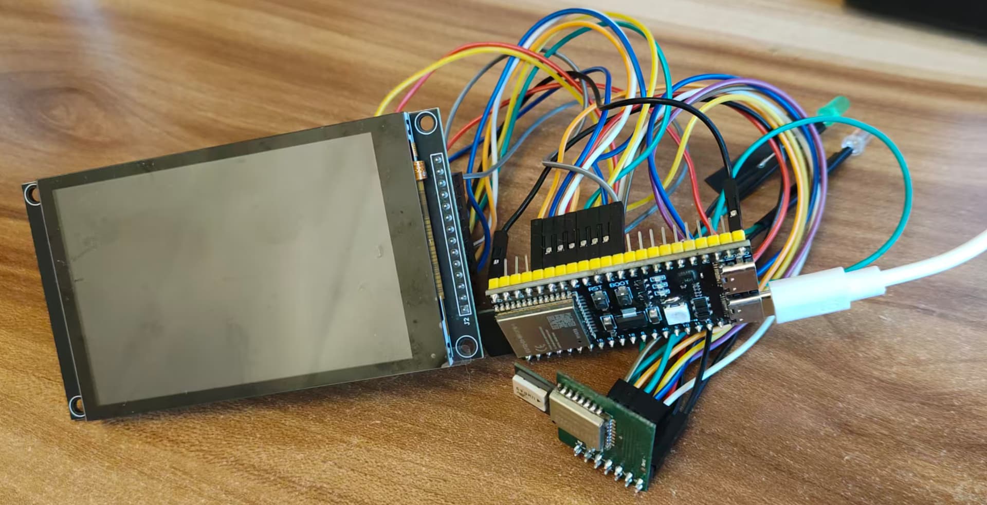
Since I decided to calculate coordinates on the Tag, I chose the ESP32-S3 as the MCU. This MCU has a 240MHz dual-core, offering strong computational power. Because the planned Tag will have multiple functions, such as an LCD screen (or OLED/e-paper display), a 3D accelerometer, an electronic compass, a fuel gauge, DC charging, etc., and the selection of related chips has not been finalized, I did not design a dedicated PCB. I am using an ESP32-S3 development board and connecting other functional modules with jumper wires for simplicity. I plan to design the board once the program is mostly done and the external modules have been tested and confirmed.
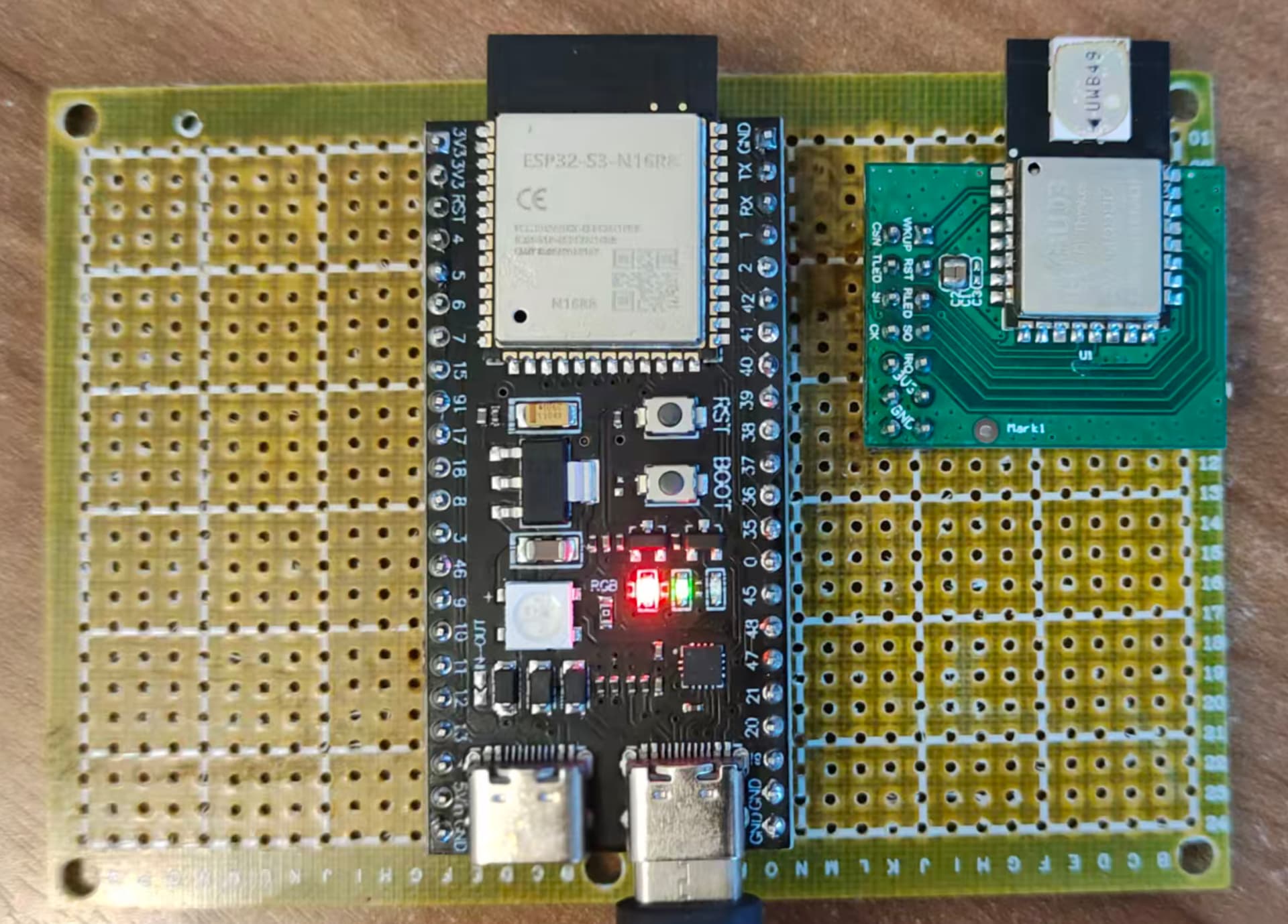
Later, I found the jumper wire setup to be too messy, so I switched to a perfboard, soldering the ESP32-S3 development board and the DW3000 module onto it and powering it with a power bank. This made the setup much cleaner.
Which Programming Language: C vs C++
Choosing between C and C++ for the ESP32-S3 firmware was a dilemma.
I have used both C and C++ in my past career. I have used C more extensively; on one hand, I started using C in college, and on the other hand, C has a broader application, especially in MCUs with limited resources, where C is more suitable. For example, the firmware for the Anchor and Tag in the previous Uplink TDOA positioning system was written in C. This is because the STM32F103 series has very limited resources, with small RAM and Flash sizes. C++ uses more RAM and the compiled C++ code also uses more Flash.
C is more low-level, while C++ introduces more complexity due to the handling of classes/objects. Of course, C++ classes and objects make the programmer’s coding process easier, whereas C requires the programmer to worry about more details.
Although ESP32’s IDF supports C++, its libraries and internal code are all written in C. If using C++, the programmer still needs to handle many chip-related details themselves.
Since a large part of this firmware code deals with interacting with the chip, and the business logic is relatively small, creating classes for Anchor/Tag/Message, etc., would not save much effort and could instead cause a lot of trouble. For example, an interrupt service routine must be a C function. If it needs to access properties of a C++ Anchor/Tag object, it involves accessing C++ code from C code, or object creation and destruction, which is too complicated.
After writing some code in C++, I found it awkward. Eventually, I switched to writing the firmware in C.
UWB Packet Reception
Since I am using the DW3000, the previous DW1000 driver is unusable. I am now using a driver based on the one provided by Qorvo for the DW3000, with appropriate modifications to adapt it to the ESP32’s SPI.
We know that DecaWave chips have two methods for UWB packet reception: interrupt and polling, each with its advantages and disadvantages.
Polling Method
The polling method only requires checking the chip status in the program loop. If a new data packet is received, the content is read, and the program waits for the next poll.
Characteristics of the polling method:
-
Simple program structure, as all processes are handled sequentially, without interruption, and there is no need to set up critical sections/semaphores, etc.
-
Lower efficiency. If a new data packet is not read promptly upon arrival, it can interfere with the reception of subsequent packets. Therefore, each step in the program loop should minimize the MCU’s time consumption.
Interrupt Method
The interrupt method is more complex. The program runs normally until a new data packet arrives, at which point the chip triggers an interrupt, and the interrupt handler reads the new data packet.
Characteristics of the interrupt method:
-
Complex program structure. Because interrupts disrupt the normal program execution, resources that need to be accessed in the interrupt service routine might be in use. Therefore, we must set up critical sections or semaphores to prevent access conflicts.
-
High efficiency. When a new data packet arrives, an interrupt occurs immediately, and the interrupt service routine can read the new data packet contents immediately.
My previous Uplink TDOA design used the polling method; this time, I switched to the interrupt method.
I created a FreeRTOS task, task_uwb_chip, responsible for interacting with the DW3000.
After receiving a new positioning data packet, the interrupt handler immediately places it into a message queue. Another task, task_uwb_message_process, is responsible for processing it.
UWB Message Types
Since this is for research, to quickly establish working conditions, I did not re-develop the Anchor. Instead, I utilized the Anchors from the original Uplink TDOA positioning system. I modified the Anchor firmware to add a message type, DLClockSyncMessage. The “DL” stands for Downlink, indicating it is the clock synchronization packet for Downlink TDOA. This packet is based on the original clock synchronization packet, but in addition to clock synchronization information, it also includes the Anchor’s coordinate information.
Initially, I wanted to have two types of messages: one for multi-level clock synchronization in Downlink TDOA, and another for Downlink TDOA positioning. I eventually found that the multi-level clock synchronization packet for Downlink TDOA can be used directly for positioning, eliminating the need for a separate positioning data packet. However, the multi-level clock synchronization packet can be split into two: one purely for clock synchronization, and another for transmitting Anchor information, such as the Anchor’s coordinates/name, etc. The clock synchronization packet needs to be broadcast frequently, while the Anchor information packet can be broadcast once every few seconds or minutes.
Creating a Data Packet Queue for Each Anchor
This is a crucial step.
Unlike Uplink TDOA, where the Tag sends one data packet and various Anchors receive it, the RTLE can immediately calculate the coordinates based on the time difference of arrival (TDOA) derived from the timestamps of when the Anchors received the packet.
In Downlink TDOA, the Anchors send the data packets, and the Tag receives them. These packets cannot be sent simultaneously, nor can the Tag receive them simultaneously. Therefore, the Tag receives data packets from different Anchors separately.
I created a queue for each Anchor. The data packets in this queue are those received by the Tag that originated from the corresponding Anchor. These packets are arranged sequentially.
When a new data packet arrives, it is added to the packet queue of the corresponding Anchor.
When calculating coordinates, the latest packet from each Anchor is extracted to participate in the calculation.
Data Packet Timestamp Handling
Since the packets participating in the calculation were sent and received at different times, a “normalization” process is required.
We calculate the coordinates based on the difference in the Time of Arrival (TOA), which is fundamental. Therefore, we need to find the difference between the time taken for the radio wave to travel from each Anchor to the Tag.
If we assume the Tag’s local time is the standard time (i.e., a unified time the same as all Anchors), then subtracting the standard time stamp of when a packet was sent from the Anchor from the Tag’s local time stamp of when that packet was received yields the time taken for that packet to travel from the Anchor to the Tag.
The previous assumption that the Tag’s local time is the standard time is practically impossible. However, because the Tag receives the DLClockSyncMessage from various Anchors, the Tag can also perform clock synchronization with each Anchor. We can choose a more accurate Anchor as a benchmark and convert the Tag’s local time into a “standard time” based on that Anchor. This way, we can obtain a “standard time.”
Theoretically, this “standard time” is not mandatory. From the previous explanation, it can be seen that using the local time directly as the subtrahend is acceptable. If the Tag’s local clock has the same rate as the Anchor’s time, only the starting point is different, so using it directly as the subtrahend is fine. The reason for converting to a “standard time” is twofold: (1) Even after factory calibration, there are subtle differences in the clock rates between the Tag and the Anchors, and these differences lead to errors; (2) The DW3000’s timer is 40-bit, and it will wrap around after some time. We might encounter a situation where some timestamps are near the higher end of the 40-bit range, while others have wrapped around and are near the lower end. For example, the sending timestamps of a few Anchor packets are slightly less than $0xFFFFFFFFFF$, and the sending timestamps of other Anchor packets are slightly greater than $0x0000000000$ because the counter has wrapped around. For wrapped values, we add $0x10000000000$ so they can be compared. If we directly use the local time as the subtrahend, handling values at the counter boundary becomes complicated, and it’s difficult to judge whether $0x10000000000$ should be added to the result of the subtraction.
Coordinate Calculation
We extract the latest data packet from each Anchor, calculate the time taken for each Anchor to travel to the Tag (this time is not the precise travel time), and then pairwise calculate the travel time difference. This “difference in travel time” is accurate.
Then, we can use a coordinate calculation algorithm to process these time differences and calculate the Tag’s coordinates. I used two algorithms: Least Squares Method and Quadtree Search Method (2D).
In the Uplink TDOA RTLE coordinate calculation, the Quadtree Search Method was more accurate than the Least Squares Method, but in this research, the accuracy of the Quadtree Search Method seems to be poorer.
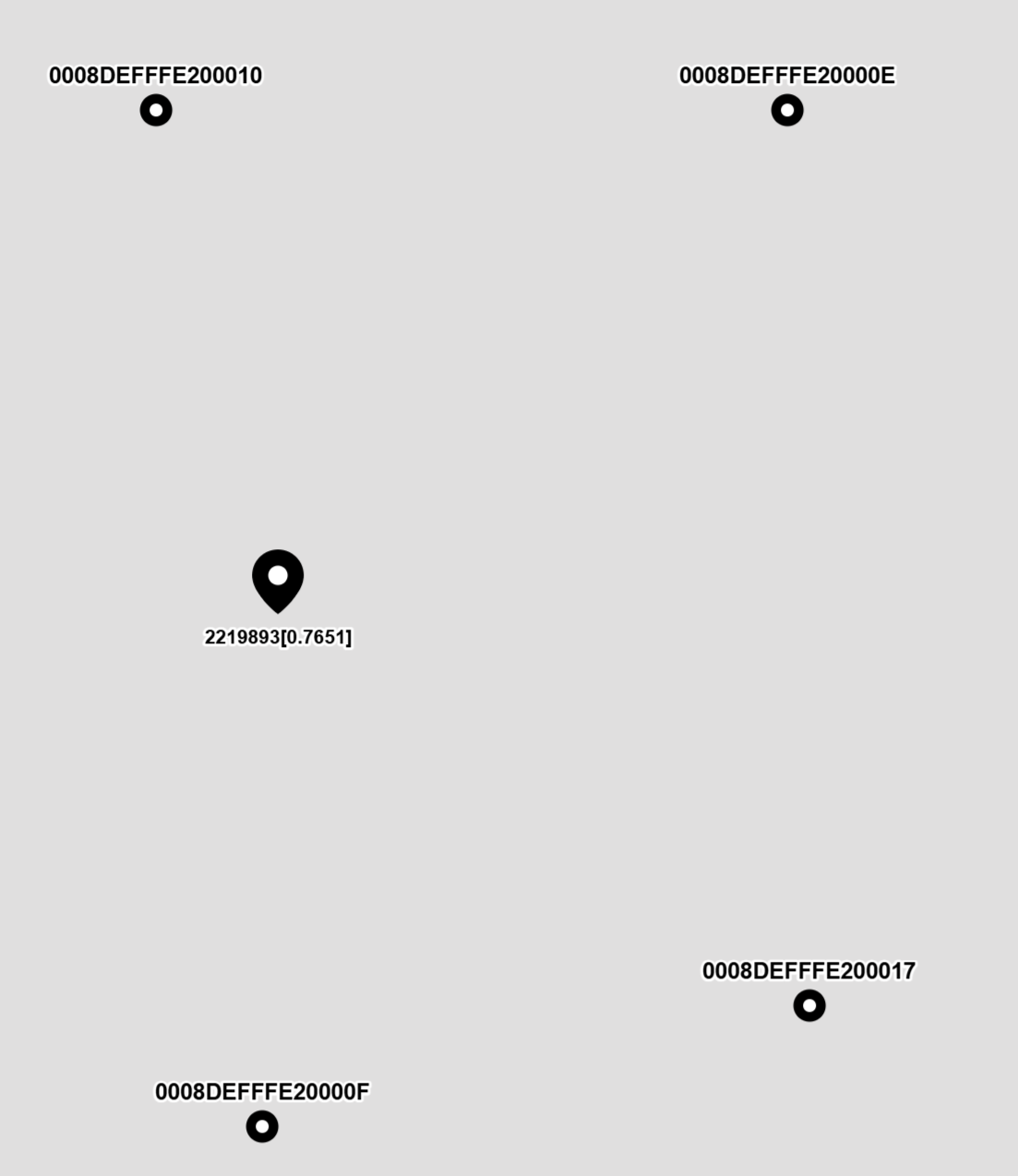
I displayed the calculation results on a map; the image above is a screenshot of the calculation results.
Next Steps
For the research of Downlink TDOA, it is fundamentally successful! However, there is still a lot of work to be done for future productization.
-
Improve the accuracy of multi-level clock synchronization. One source of error in the calculated coordinates is the insufficient accuracy of multi-level clock synchronization. Every level of clock synchronization involves three stages: packet sending, packet transmission, and packet reception, all of which can introduce errors (in fact, this error is also the main source of error in Uplink TDOA). Furthermore, multi-level clock synchronization introduces error at every level, theoretically doubling the error with each additional level. A mechanism needs to be researched to reduce this error.
-
Influence of antenna delay. This point should technically be included in the previous one, but it is listed separately because it is important. The DW3000 has a default antenna delay value, but it is not very accurate. When a clock synchronization packet is sent from an upstream Anchor, it is affected by the sending Anchor’s “Transmit Antenna Delay.” When the receiving Anchor receives the clock synchronization packet, it is affected by the receiving Anchor’s “Receive Antenna Delay.” If the antenna delay is inaccurate, for example, an error of 10 cm, this error will affect all subsequent Anchors along the clock path.
-
Improve stability. During testing, the Tag often “drifts,” meaning the coordinates frequently deviate significantly from the correct position. During packet reception, erroneous timestamps are often received, and we need to identify and filter out these incorrect timestamps. I have used a filter to do this, but there are still some issues. I need to research the data processing of the filter to effectively filter out erroneous timestamps.
-
Test other coordinate algorithms. Compare the calculation results using the Chan, Taylor, Chan-Taylor, and Gauss-Newton algorithms.
-
Currently, for the research phase, the Anchors are realized by modifying the code of older STM32-based Anchors. The next step will be to use the ESP32-S3 as the MCU to implement the full-featured Downlink TDOA Anchor. I also plan to add TWR (Two-Way Ranging) positioning so that the Anchors can self-position. Once the positions of three Anchors are determined, the positions of the other Anchors can be calculated autonomously to reduce the deployment workload.
-
Anchor Locking. Because the Tag might be moving, it might not receive signals from distant Anchors at certain positions, but it might receive signals from new Anchors. Similar to GPS, a GPS receiver might lose the signal of one satellite or acquire the signal of a new satellite. A locking mechanism needs to be added to ensure that the data packets from the Anchors participating in the coordinate calculation are the latest.
-
Adding External Module Functions. For example, Li-ion battery charging (using a DC-DC charging chip to reduce heat, increase charging current, and use a temperature protection mechanism to ensure charging safety), LCD display (or OLED/e-paper, capable of receiving and displaying SMS TEXT from the control center, and maps), 3D accelerometer + electronic compass (for auxiliary positioning, and putting the Tag to sleep based on movement status to save power), fuel gauge (to monitor remaining battery capacity), buzzer, and vibrator motor. In the future, a microphone and speaker could even be added for intercom functionality.
-
Possible Tag Interfaces: The Tag could be designed with an interface similar to commercially available GPS modules, sending coordinate information to a host via UART. A GPS module could be integrated into the Tag to use GPS outdoors and UWB indoors. It could also be integrated into an Android device to utilize existing navigation software or a developed navigation APP.
-
Auxiliary Software:
-
Antenna Delay Calibration: We need to calibrate the antenna delay for every Anchor.
-
Anchor Configuration Program: Configure the Anchor’s parameters and upgrade its firmware via USB or network.
-
Tag Configuration Program: Configure the Tag’s parameters and upgrade its firmware via USB or network.
-
Frequency Calibration: The crystal oscillators used inside the DW3000 module may have subtle frequency differences. We use a frequency calibration program to ensure that the frequencies of the DW3000 used by the Anchor and Tag are as close as possible.
-
Simple Server: This simple server software can receive location data sent by various Tags over the network and allow displaying the coordinates of all Tags on a map using a browser. It can also send SMS TEXT to the Tag and control the Tag’s buzzer to sound or vibrator motor to vibrate.
-
Several production-related software tools, such as factory configuration and registration (firmware flashing, default configuration, product information registration in the database), and nameplate printing (for printing product nameplates).
Other Auxiliary Work
Tag Network Interface
In the Tag’s firmware, I implemented a webserver with WebSocket. This allows me to create a few HTML pages and use JavaScript to create a WebSocket connection with the Tag to display some data in the browser. I previously wrote an article about data visualization in positioning research. I displayed the data received by the Tag in a curve chart, which provides an intuitive view of what is happening.
Tag’s firmware also includes a TCP Client, which automatically connects to a TCP Server and sends some important messages I am interested in.
TCP Message Aggregator
I wrote a TCP message aggregation tool in C++ (actually written by AI provided by Cursor). Its function is to provide both a TCP Server and a Web Server with WebSocket. It forwards messages received from TCP Clients to WebSocket clients.
For example, there are several Tags that automatically connect to the TCP Server and send successful positioning messages. The JavaScript in the browser creates a WebSocket connection to the Web Server. The Tag’s successful positioning messages are forwarded to the browser’s WebSocket client, and the browser’s JavaScript displays the Tag’s coordinates.
When Cursor wrote this program for me, I just described my requirements in as much detail as possible in the documentation I provided to Cursor.
Vite Frontend
Initially, I used curve charts to observe the Tag’s data, and even the coordinates calculated by the Tag were observed using curve charts, but this felt less intuitive. In the previous Uplink TDOA positioning system, I designed a page that used OpenLayers to demonstrate the positioning effect. So, this time, I also planned to use OpenLayers as the map frontend for displaying the positioning effect.
I used OpenLayers 3 before, and the JavaScript code was all written by hand without the aid of tools like Node.js. This time, I used Cursor for AI programming. I first wrote a detailed functional requirement document and then asked Cursor to help me write the code.
To my pleasant surprise, Cursor wrote the code correctly on the first try. Later, I realized I forgot to mention the WebSocket requirement, so I asked Cursor to add a WebSocket connection. Initially, the WebSocket connection was opened and closed with two buttons, but I later asked Cursor to change it to automatically connect to WebSocket when the page opens.
I also had Cursor add a timestamp next to the Tag icon, so the change in time is clearly visible. The displayed timestamp was later modified to include the error value, showing the error status for different coordinates.
AI Programming
AI programming is now very powerful and has reached a practical stage. I have subscribed to a Cursor Pro membership, paying $20 per month. Adapting to using AI for programming takes some time; I often forget to use the AI and just write the code myself. In the future, I plan to let the AI do the coding as much as possible, while I focus on planning the program structure and clearly communicating the requirements to the AI.
Here are a few examples of AI programming:
-
The “TCP Message Aggregator” program mentioned earlier in this article was written using Cursor, and I only made minor modifications. Even the decision to use ASIO as the network underlying component was made by the AI.
-
The “Vite Frontend” mentioned earlier was also written by Cursor, and I did not make any modifications. When I found that I needed to add or modify a function, I would tell Cursor in text where to make the change and what result I wanted, and it would help me implement it.
-
I also had Cursor write the code for several C files in the Tag firmware.
-
The Anchor configuration program for the old positioning system was written in Delphi, which I have used for over twenty years. Since fewer people use Delphi now, I tried using Cursor to translate the Delphi code of this program into C++ and QT. After some effort, I got a working C++ program. However, many functions were incorrect and could not be used directly. This was my first time using Cursor, and perhaps I hadn’t fully utilized its capabilities. However, I found that the C++ code it wrote contained many valuable QT usage patterns. Since I am new to QT and have written few QT programs, my usage is conservative and barely functional. Cursor, on the other hand, is like a novice with extensive knowledge; it just doesn’t know what to do until you explicitly tell it, and then it quickly helps you implement it.
I also found that Cursor is particularly convenient for configuring development environments. For example, if you want to write a C++ and QT program, just tell it, and it will help you write the code and configure the appropriate development environment so that the program can be built successfully. You don’t have to worry about missing an environment variable, a missing software installation, or configuration file syntax; it handles everything for you.
About the Author:
> ![]() I have 10 years of experience using Decawave chips. I am currently selling UWB positioning solutions using Uplink TDOA technology (https://en.uwbhome.top). This is an already mass-produced product solution that has been applied in many fields and verified by a large number of users. By purchasing our solution, you can skip the high-risk fundamental research and development phase and move directly into production and sales.
I have 10 years of experience using Decawave chips. I am currently selling UWB positioning solutions using Uplink TDOA technology (https://en.uwbhome.top). This is an already mass-produced product solution that has been applied in many fields and verified by a large number of users. By purchasing our solution, you can skip the high-risk fundamental research and development phase and move directly into production and sales.
> ![]() Recently, I have been researching UWB positioning solutions using Downlink TDOA technology and have implemented the basic functions. If you are interested, you can invest in this solution.
Recently, I have been researching UWB positioning solutions using Downlink TDOA technology and have implemented the basic functions. If you are interested, you can invest in this solution.
> ![]() If you have any UWB project cooperation needs, please contact me. WeChat/CellPhone: +86 18985041403, Email: bd8ncf@gmail.com.
If you have any UWB project cooperation needs, please contact me. WeChat/CellPhone: +86 18985041403, Email: bd8ncf@gmail.com.