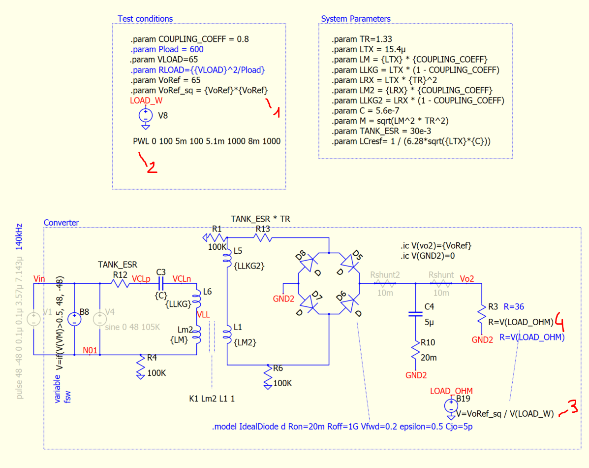
I’m trying to simulate a system with a variable load. The load is resistive and I want to define the load power and then compute the necessary resistance for this power.
However this simulation takes a long time, 119s to be precise. If I used a fixed resistance (of the same value, just to be sure the resistance value does not affect), the simulation is super fast, at only 6s.
Could you please provide some indications on how to implement a computationally effective variable load? Or any tips to improve my current implementation?
Also, in the same line, I’m using C blocks and it has a significant impact on simulation time. These blocks have some ‘heavy’ calculations but they are run only once every 50us or so and thus I feel they shouldn’t have such a significant impact. The problem is how to ensure they are run at a given frequency, I did it by using a squarewave at the input and in the code I only perform the calculations and evaluations in case that there’s a flank in the clock. I’m not sure if there’s a lighter implementation, any advice is welcome.
Using a square-wave source to drive a C-Block may have issues. See C-Block Basics #5 on my GitHub repository for an explanation and sample code to generate the clock inside the C-Block.
Thanks for the information. If I understood it correctly, the concern would be that QSPICE decides there’s not much going on and thus might skip clock pulses, although you did mention that official support suggested adding a cap to the clock source to ensure pulses are not skipped. While skipping clock pulses is of course to be avoided, the question was more into optimizing simulation speed. And actually adding this cap at the output of the clock, was very detrimental to simulation speed.
I have no idea how SPICE works behind the curtains but to me it feels like with both problematic elements in my question (variable resistance and C blocks) instead of being computationally demanding, these items appear to cause a decrease in the timestep, which of course leads to more simulation time.
Just by looking at your schematic, it is very hard to tell. I am not completely sure if the behavioral resistor is causing the long simulation time. Is there a possibility that the simulation encounters a difficult situation at the transient of the behavioral resistor?
This simulation with complex GND setting which generally not required in simulation.
I’ve been working on it today and now it’s very fast, I did many changes, my best guess would be a refactoring where I separated a C block into 2. The block was originally triggered by a clock but used simulation variable time t for some calculations kind of simulating HW and I think that caused the block to be run all the time even though it had the clock input. Hard to enable/disable as the change is not straightforward but now it’s good.