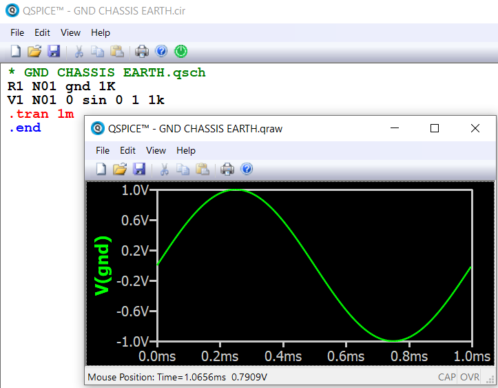
When I tried to create a net named chassis, QSPICE automatically converted it to a chassis ground symbol, which is nice. However I noticed that the components between this chassis symbol and GND are ignored in the simulation (I got a “Ignoring shorted resistor” message). I was wondering if chassis is treated as GND or node 0.
Use “View” > “Netlist”, you can confirm what exactly is going on.
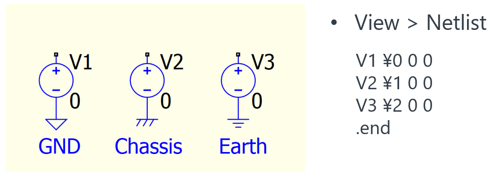
GND and Chassis symbol both interpreted to node name 0.
And resistor with both nets connect to same node is ignored.
In verification, synonyms only apply when schematic to netlist, but not a direct netlist .cir simulation. For example, if .cir calls these net names, they will be treated as a normal net name and not be interpreted to node 0.
So this “label” “gnd” is not conected to “0”
Then R1 don’t “close” the circuit and in “gnd” you have the V1 voltage (as you show in the graph)
Really I don’t understand the problem cause imho it’s normal this behavior.
Another thing is how to have to different grounds as in a SMPS (separated with a decoupling capacitor). I understand the theory but not really sure how to put in practice. Thanks!
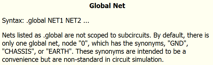
The situation is that, if you type “gnd” or “chassis” or “earth” in schematic, it will automatically convert to “0” in netlist. The idea of spice simulation is that, the simulation always run based on netlist. The schematic is just a GUI to convert a graphical circuit into a netlist. If you are familiar with netlist, you actually not requires to have a GUI for graphical circuit. So, if you are working in schematic, net name “gnd”, “chassis” and “earth” are all convert to “0” in netlist. This is the first message.
For the second message, I just shown you that, if you are working directly on a netlist. “Gnd” will just interpret as a net name, it will not be treated as 0.
So, as long as you are only working from schematic, you cannot define a net name as “gnd”, “chassis” or “earth”, as they all automatically converted to 0 in schematic to netlist conversion.