Hello,
I used the following code to capture CIRs, (found here in the forum)
/// store magnitudes in float array CIRValues
bool readDW3000CIRData(int32_t *realvalues, int32_t *imgvalues ,int len, int offset) {
// DW3000 is 3 byte I, 3 byte Q (18 bits per value) with a 1 byte blank at the start.
// DW1000 is 2 byte I, 2 byte Q with a 1 byte blank at the start.
//	Max of 992 or 1016 points (16/64 prf)

if ((len + offset)>1016)
    len = 1016-offset;
if (len <1)
    return false;

const int bytesPerValue = 6; // dw3000


uint8_t cir_buffer[1016*bytesPerValue+1]; // worst case

dwt_readaccdata(cir_buffer, len*bytesPerValue+1, offset);
int byteAddress = 1;
for (int i=0;i<len;i++) {
    int32_t iValue = cir_buffer[byteAddress++];
    iValue |= ((int32_t)cir_buffer[byteAddress++]<<8);
    iValue |= ((int32_t)(cir_buffer[byteAddress++] & 0x03)<<16);

    int32_t qValue = cir_buffer[byteAddress++];
    qValue |= ((int32_t)cir_buffer[byteAddress++]<<8);
    qValue |= ((int32_t)(cir_buffer[byteAddress++] & 0x03)<<16);

    if (iValue & 0x020000)  // MSB of 18 bit value is 1
        iValue |= 0xfffc0000;
    if (qValue & 0x020000)  // MSB of 18 bit value is 1
        qValue |= 0xfffc0000;

    realvalues[i]=iValue;
    imgvalues[i]=qValue;
}
return true;
}
void printCIR() {
int CIR_length = 900; // Number of complex CIR samples we want to read
int32_t realSample[CIR_length];
int32_t imagSample[CIR_length];
readDW3000CIRData(realSample,imagSample,CIR_length,0);
char tmp[16];
int len;
reporter_instance.print(“\nCIR_real_values = [”, 20);
len = snprintf(tmp,16, “%ld”, (realSample[0]));
reporter_instance.print(tmp, len);
for (int i = 1; i < CIR_length; i++) {
len = snprintf(tmp,16, " %ld", (realSample[i]));
reporter_instance.print(tmp, len);
}
reporter_instance.print(“]\n”, 2);
reporter_instance.print(“\nCIR_imag_values = [”, 20);
len = snprintf(tmp,16, “%ld”, (imagSample[0]));
reporter_instance.print(tmp, len);
for (int i = 1; i < CIR_length; i++) {
len = snprintf(tmp,16, " %ld", (imagSample[i]));
reporter_instance.print(tmp, len);
}
reporter_instance.print(“]\n”, 2);
}
/* @brief ISR layer
-
TWR application Rx callback -
to be called from dwt_isr() as an Rx call-back
*/
static void mcps_rx_cb(const dwt_cb_data_t *rxd)
{
#define MAX_MSG 2
#define MAX_MSG_LEN 128
static uint8_t message[MAX_MSG][MAX_MSG_LEN];
static dwt_mcps_rx_t rx[MAX_MSG];
static int idx = 0;
struct dwchip_s *dw = rxd->dw;
const struct dwt_mcps_ops_s *mcps_ops = dw->dwt_driver->dwt_mcps_ops;
struct dwt_mcps_runtime_s *rt = dw->mcps_runtime;

struct dwt_mcps_rx_s *pRx = &rx[idx];
uint64_t ts, timebase64;

pRx->rtcTimeStamp = Rtc.getTimestamp();

/* RX TS in RCTU of local timebase */
ts = mcps_ops->get_timestamp(dw);

/* convert local timebase in RCTU */
timebase64 = timestamp_dtu_to_rctu(dw->llhw, get_timebase_dtu(dw));

pRx->timeStamp = (ts + timebase64 + rt->corr_4ns) & 0xFFFFFFFFFFULL;

pRx->flags = 0;

if (rxd->datalength)
{
    pRx->len = MIN(rxd->datalength, MAX_MSG_LEN);
    pRx->data = (uint8_t *)&message[idx];
    struct dwt_rw_data_s rd = {(uint8_t *)pRx->data, pRx->len, 0};
    mcps_ops->ioctl(dw, DWT_READRXDATA, 0, (void *)&rd);

    int16_t cfo;
    mcps_ops->ioctl(dw, DWT_READCLOCKOFFSET, 0, (void *)&cfo);

    pRx->cfo = cfo;
    /*Below Xtal trimming can be executed in the upper layer: rx[idx].cfo*/
    int cfo_ppm = (int)((float)cfo * (CLOCK_OFFSET_PPM_TO_RATIO * 1e6 * 100));
    dw->mcps_runtime->diag.cfo_ppm = cfo_ppm;


    printCIR();
}
else
{
    // most likely an SP3 packet --> no data
    pRx->len = 0;
    pRx->data = NULL;
    pRx->flags |= DW3000_RX_FLAG_ND;
}

dw->rx = pRx;
#if 0
if (data->rx_flags & DW3000_CB_DATA_RX_FLAG_AAT)
rx->flags |= DW3000_RX_FLAG_AACK;
#endif
idx = (idx == MAX_MSG - 1) ? 0 : idx + 1;
if (osSignalSet(mcpsTask.Handle, MCPS_TASK_RX) == 0x80000000)
{
    error_handler(1, _ERR_Signal_Bad);
}
}
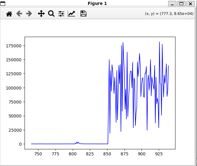
Once the CIRs captured, I obtained the following result for a given CIR,

I would like to know why there is a significant magnitude spike around the sample index 780 and not before, I would like to know what represent the magnitudes before the spike.
Also the attached figure shows somehow that I am not capturing everything, there are some signals neglected. After the first spike, there are other spikes that represent reflected signals which I am interested in as well, how can I capture those as well ?
Thank you for your help in advance.