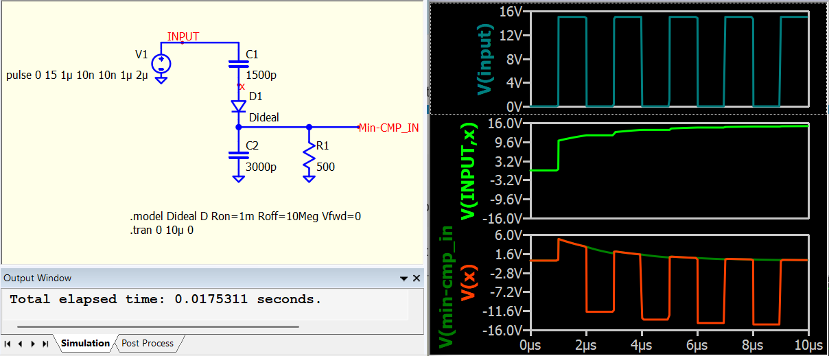
Why does it not make sense? When a diode is added, C1 no longer discharges when the pulse input drops to 0V. The voltage across C1 continues to charge in each +15V duration until the capacitor is fully charged up to 15V. It is equivalent to having a +15V DC source in the opposite direction to V1, causing V(x) to settle between 0V and -15V. The diode blocks the negative voltage, resulting in this circuit having 0V at C2. V(min-cmp_in) equals +positive part of V(x), and that why you get such a waveform. The key is, C1 cannot be discharged in this circuit.
Refer to this post for what you should do to upload files
Qspice Forum - New User to Basic User (File Upload) - QSPICE - Qorvo Tech Forum