Hello:
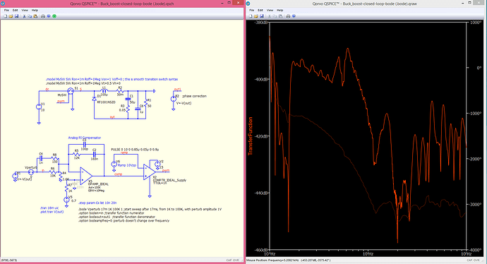
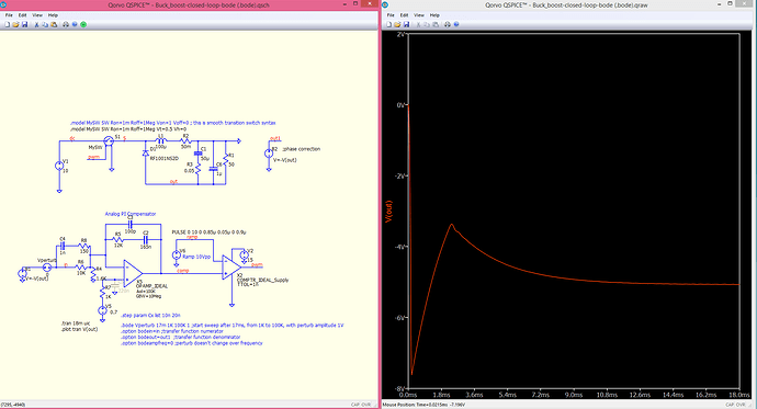
I’m trying to simulate a Bode analysis in a buck-boost converter. If the transient analysis gives a realistic result, then the Bode analysis gives incomprehensible values.
Also attache your simulation file
Buck_boost-closed-loop-bode (.bode).qsch (20.7 KB)
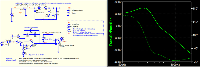
The .bode method will first run to steady state (Tsettle), but without the UIC option. If you remove UIC from .tran, this circuit won’t work, as the op-amp output can go without bounds. Here, I replace the op-amp with a Qspice RRO device, which can limit the output voltage. In general, boost or buck-boost is controlled with current mode, but this is a voltage-mode controller, and we have to add some limits to prevent the current from shooting up unreasonably.
I change .bode from 1V to 0.1V… your output is just ~5V, having a 1V perturbing source may be too much.
19051-4-KSK.qsch (23.4 KB)
1 Like


