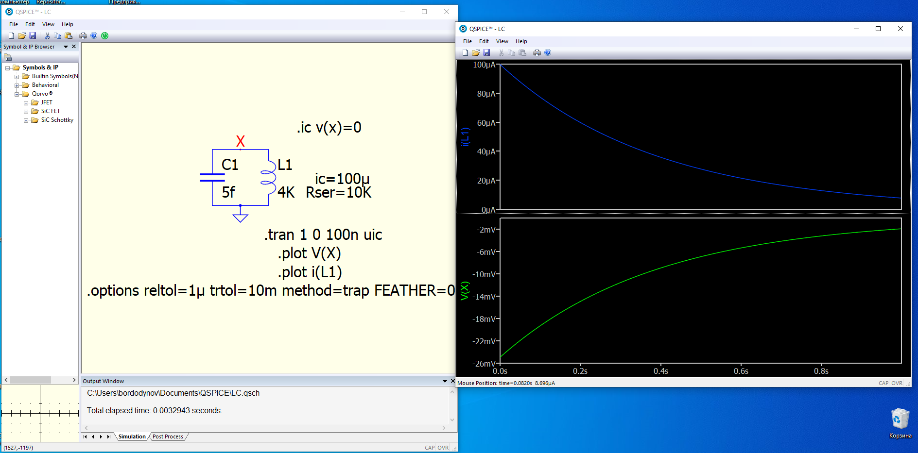
I tried to calculate a quartz oscillator model. It did not work. Then I took the LC resonant circuit, set the initial current of 100 µA. I ran the simulation and did not see oscillations. The current through the inductance was falling along the asymptote.
Bordodynov
Very Cute!
What is happening is that you have a non-physical circuit: It isn’t possible to make a 4,000 Henry inductor shunted only with 5 femtoFarad capacitance, and a Q that goes to infinity as frequency does.
All SPICE programs add some conductivity to make the circuit solvable with robotically set up device equations, even though QSPICE can solve your specific circuit without any. The only time I’ve seen SPICE’s gmin be an issue is when simulating dielectrically isolated input stage opamps, where currents are in the femtoAmp range. Any electrometer circuit usually requires manually setting gmin to something less than the default 1e-12mho.
QSPICE dampens reactances if no damping is given. This is intended to be useful, which it is. The time constant used for capacitors defaults to over 30,000 years. I had tried different values, like the age of the universe, but a time constant that covers the period since the last ice age seemed safe, though honestly, I think any time constant greater than 100 years is perfectly acceptable. Transistors were only invented 76 years ago. I used a shorter time constant for inductors since Thévein equivalents are more difficult to solve.
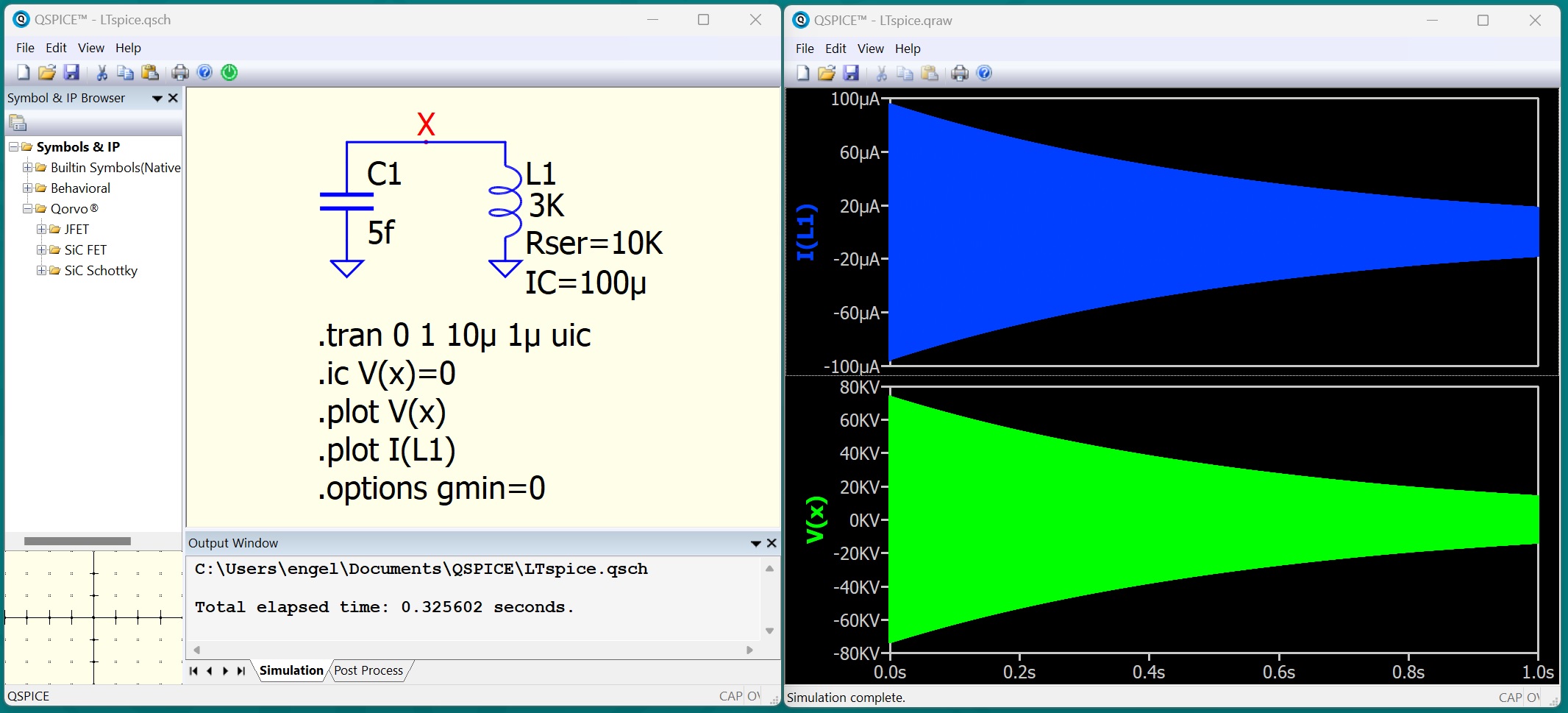
Anyway if you add “.options gmin=0” you get the solution you might have been looking for. Remove Rser=10k if you want to see it ring forever without any damping.
–Mike
1 Like
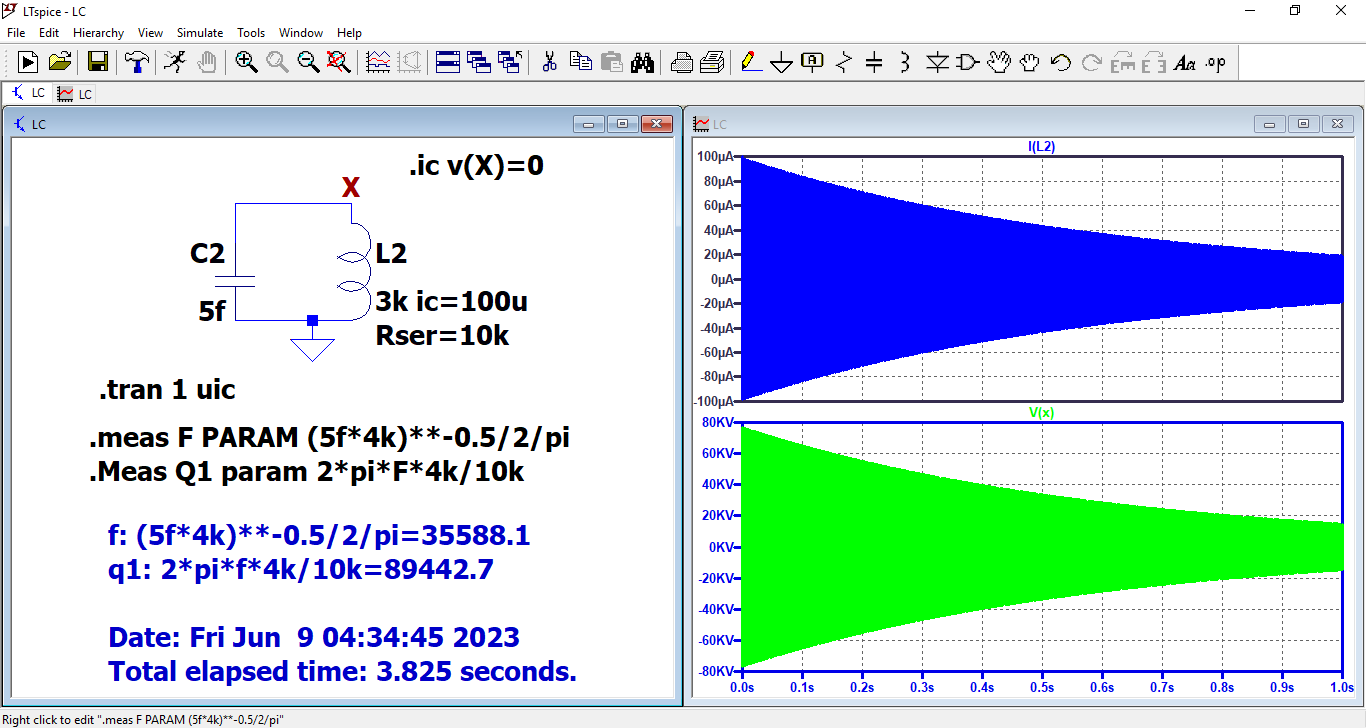
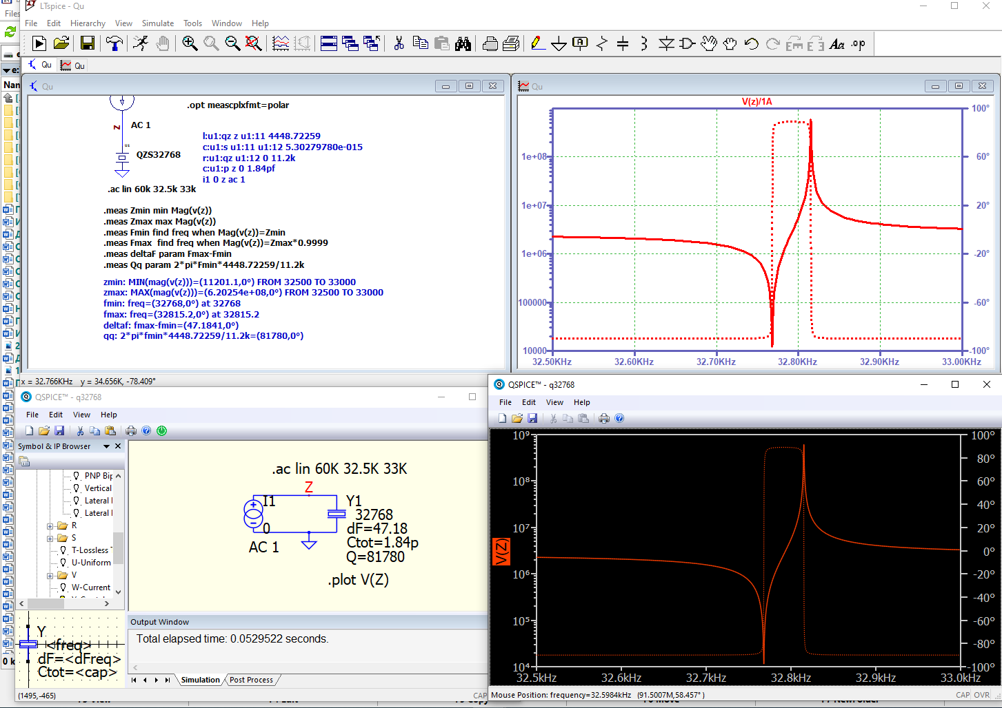
This circuit is the equivalent of a 35 kHz quartz resonator.
LTspice calculates it without any adjustments.
I will try to set the Rpar for these two elements to about 1.e38 without setting .options gmin=0.
I have many models of quartz resonators in my collection and it would be more correct to use Rpar.
Thanks for the advice.
Bordodynov.
LTspice also adds damping but you can go into the control panel and turn it off. The damping in QSPICE does not affect any physical circuit, including a crystal. QSPICE scales the damping off gmin, which is more reasonable approach. If you turn gmin off you can duplicate the LTspice result in QSPICE. It just simulates 10x faster in QSPICE than LTspice:
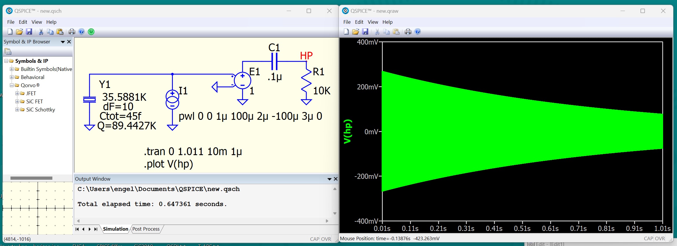
But I said you don’t have to turn off the damping for a crystal circuit. That is correct. You don’t have a physical model of a crystal. Fortunately, QSPICE supports the crystal as a native circuit element. The input parameters are the resonant frequency, offset between the parallel and series resonances, Q, and the total capacitance as one would get from a DC LCR meter. If Q is not specified, it’s default value isn’t bad for MHz crystals.
For your crystal, I had to guess values, since the information isn’t available from your model. I took the total capacitance as 10x the series resonate value. For the shift between series and parallel resonance, I took 10Hz for a watch crystal. There are problems with the way you modeled the crystal. It doesn’t have a series resonance. It leaks like a 10k resistor. And every crystal I’ve worked with has more capacitance.
Of course, a real crystal is a little tricky to get ringing. If you start with a DC voltage IC, then it will just sit there with that voltage across it and not ring. That’s the way a real crystal works. In this simulation, I start it ringing with a spike of current and then filter off the DC offset left with a high filter.
1 Like
It is a pity, of course, that there is no alternative to setting the quality factor Q. For clock quartzes, they specify Rser. Rser corresponds to a well-defined quality factor. In LTspice I gave the quality factor calculation based on Rser.
Oh, I think there’s less room for interpretation in measuring Q than Rser – that Q is the more fundamental description. Rser requires assuming a circuit.
Well, I guess you would measure Rser at the series resonance, but that ignores the degradation in Q from the parrallel loss.
Ask your crystal vendor for Q.
Anyway, I think having a crystal device as a native circuit element like it is in QSPICE is overdue.
–Mike
3 Likes
I absolutely agree that goodness Q is more comprehensive. But in real circuits, a resistor is included in parallel with the resonator. For a 32768 clock quartz the value of this resistor is about 20 Mohms. Suppliers of such clock quartzes indicate the maximum resistance. There is no mention of the quality factor. They also indicate the ratio of the crystal holder capacity to the internal (fictitious, equivalent) capacity K=200 -400. For LTspice I made a subcircuit which uses Freq, C0 and K.
But I liked the idea with your parameter set. Maybe I will make a similar subcircuit for LTspice.
Alexander.
1 Like
Oh, before you were all about the series resistance. I added the ability to set Q with Rser. If both Rser and Q are specified, QSPICE will add a parallel loss to meet the Q specification. I think I’m OK leaving it this way because Q can be directly measured. Rser can be some some extent. A vendor’s parallel resistance is ambiguous to me. It could be he’s specifying the quality of the dielectric at DC(what can be directly measured) or it could be an indication of parallel loss at the resonate frequency, which would be useful.
Whether Q, Rser, Rpar is given depends on the mfg. Abracon Corporation specifies Q: abracon.com/datasheets/Oscilent/223.pdf
I think you should ask your vendor for the value of Q.
–Mike
1 Like