I’m day one for a UWB location project. I’m seeking the recommended Qorvo hardware components that i’ll need to start out with for the tag and anchors.
(Is there a “Type 2AB UWB + Bluetooth®” available yet?)
Scope of project:
Location of a mobile tag indoors and outdoors (200ft max.) Downlink TDoA RTLS mode only
2 dimensions only
Anchors wired to mains power (no data cable between anchors)
Anchors to “auto” locate themselves for initial set-up
Tag fully Autonomous (set-up/control params via BlueTooth)
Tag to run with an on-board location engine and custom C - code
application (ie: point-in-polygon, etc)
Any start up thoughts/suggestions on this would be appreciated!
Thank-you!
NOTE:
Anchors can ONLY be attached to building (stored X-Y property line points are stored in tag during set-up)
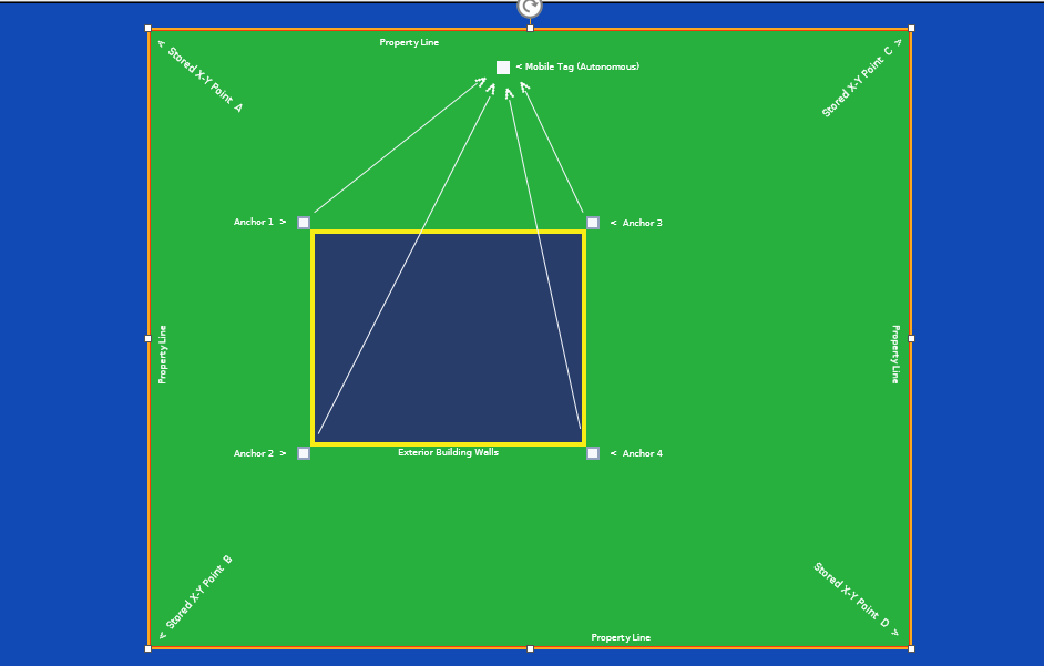
… In reading on setting up the anchors for an outdoors downlink only layout , meeting the minimum of three (3) stable RF anchors is problematic for a typical rectangular residential home for this application (dog containment system … “invisible fence”).
With a main prerequisite that all anchors be attached to the building structure ONLY … this,as you can see in the pic above, at best, at least one of the RF paths required is always thru the massive attenuating obstructions within the building itself (NOT GOOD!) : (
I was pondering a different paradigm … two fixed anchors with the third leg … the tag itself!
This would result in a “clear RF view” from all points involved.
This works great for calculating the distance to the tag using the known “fixed” base line length between the two (in line of sight) fixed anchors and the received downlink timestamps at the tag.
The problem with this method is that it doesn’t give you the directional orientation from the anchors base line to the tag … it could be to the left of the base line (as shown in pic below) or to the right of the base line.
In essence, (depending on how you flip it) you get the true tags X-Y location point (left side) or a mirrored (ghost) X-Y location point extending equally out to the right side …, you now have to determine which one is the tags true position.
Attach four anchors (single antennas) to the four corners of the building (mains powered)
Program all anchors for a “round robin” downlink only transmission.
Store all the “fixed” anchors distances to one another in tag.
Take the autonomous mobile tag to all four corners of the property line and store their X-Y coordinates in tag … this is the “invisible fence”
Note from my pic above, the entire property line is now a defined “polygon”.
I now break this polygon into four smaller polygons (polygon area 1,2,3 and 4)
Note the 45 degree jointing of all four of these smaller polygons. This is to eliminate small sharp “slivers” of error prone angles from forming.
Looking at the pic above, you see the real location of the tag on the left side near the back yard fence line.
Remember, this true X-Y coordinate has a mirrored coordinate to the right, extending past the front yard line (we have to prove it not party to our location determination)
I can do that by running “point-in-polygon” to see if its in our current polygon area (back yard)
This also eliminates any location time stamps heard by the tag not assigned (paired) to the clear path viewed anchors responsible for tag location for that given polygon.