I’ve slightly modified the “SMPS.qsch” diagram, by adding a 50 pF capacitor at the inductor switching node:
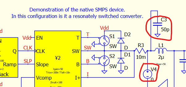
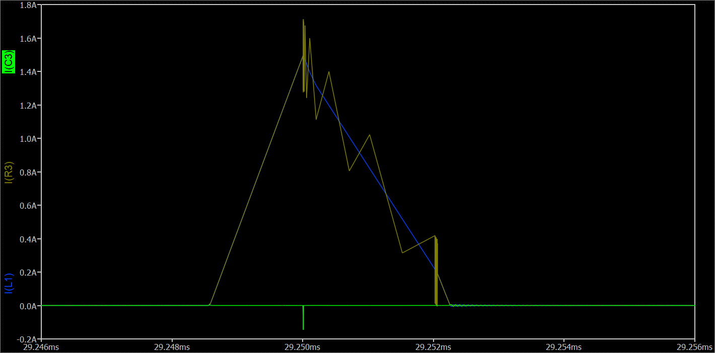
Now it appears that the current into the inductor L1 is quite different from the current into the shunt resistor R3, and this difference is not going into C3…
Where is the difference current going?
No current is flowing across V4.
That looks like trapezoidal ringing - a situation where the numerically-integrated solution oscillates about the true solution timestep to timestep. A side effect is that current monitoring can look off[1].
In a sense, it’s giving the correct answer, in that the area under each trapezoid has the correct area, but it is certainly disconcerting.
You can reduce or eliminate it by some of a combination of these methods:
- Reduce trtol(.options trtol=1)
- Reduce the maximum allow time step size(4th number on the .tran command)
- Change to Gear integration.(.options method=Gear)
The last option is the most empathic way of getting rid of it, but it also introduces the greatest error. A simulation done with Gear integration can look stable when in fact, it is not. I’ve seen IC designers go to silicon only to learn they made the mistake of using Gear integration to check the IC’s operation.
–Mike
1] Current monitoring is not really part of the solution of the circuit. It’s the node voltages that are solved for, except for the voltage sources where the currents are part of the solution. Current monitoring is done as a forensic analysis of the circuit. Current reporting can be in error even if the rest of the solution is correct. I’ll fix errors in report as they come up, e.g., today I fixed an issue in capacitor current reporting.
3 Likes