hi,
AOA board two antenna distance only 2.0154cm, why no half of wavelength 2.31cm ?
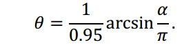
and when calc the angle, why add 1/0.95 ?
hi,
AOA board two antenna distance only 2.0154cm, why no half of wavelength 2.31cm ?
and when calc the angle, why add 1/0.95 ?
There is noise in the phase measurement, it isn’t perfect. If your noise is enough, you would flip from being just under half wavelength to being just over half, which looks like being minus just under half wavelength. Say a 175 degree true phase reads as 185 degrees phase due to 10 degrees of phase noise, which is identical to -175 degrees phase. Those produce two radically different angles in the equation. By making the antenna spacing some amount less than half a wavelength, you avoid this “flip over” effect.
In our measurements, the phase noise is about 3 degrees standard deviation. To cover +/- 3 std devs (99.7% of all points), that takes +/- 9 degrees of phase margin. Decawave built the antenna pair with a 3 mm distance margin, which is 23 degrees phase margin, about 8 std devs away, thus it should be well outside the phase noise and avoid the “flip over” effect.
Unfortunately, the receive time you get for the packet, RX_TIME, is not sufficiently accurate to disambiguate a phase wrap. To avoid phase wrap, you are limited to having the antennas closer than half a wavelength minus a noise margin.
It is an empirical fit that better describes the system performance. The non idealism comes from the two antenna affecting each other’s pattern, among other things. This is mentioned in this AOA paper:
https://www.decawave.com/sites/default/files/angle_of_arrival_estimation_using_dw1000_online.pdf
Section F talks about the fudge factor between the ideal equation (3) and the more useful actual equation (5).
The above formula differs from (3), but fits well with the results obtained using the anchor antenna array chosen for Decawave’s AOA demonstration kit. In other words, (5) gives good model of non-ideal effect described in Sec. B for the antenna array used.
Mike Ciholas, President, Ciholas, Inc
3700 Bell Road, Newburgh, IN 47630 USA
mikec@ciholas.com
+1 812 962 9408
hi, Ciholas:
Thank you very much for your quick reply.
if my AOA antenna distance less than 2.0154 cm, for example , the distance is 1.5cm,
1/0.95 should not be suitable ? how to get the right the fudge factor?
You measure the system and fit the fudge factor to the results. You can also use another formula (polynomial fit, say), or even do tabulated data with a look up table. Basically, anything that converts the measurements to the actual response will do the job.
Ideally you do this over several units to establish the baseline response outside of unit to unit variations.
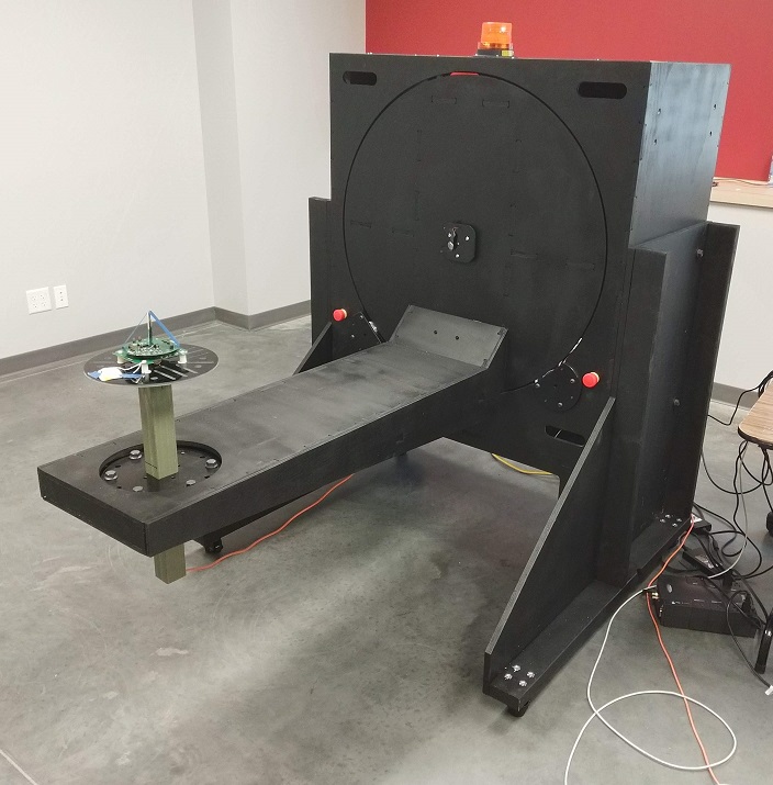
To facilitate such tests, we designed and built a 2 axis (azimuth and elevation) antenna positioner system which allows us to automated antenna measurements with a high degree of precision. Here’s a picture of it testing a long range Decawave module we are developing. The system was specifically designed for UWB measurements where you want the antenna to not change distance while it is moved so you can map the effect on UWB time and distance measurements.
Mike Ciholas, President, Ciholas, Inc
3700 Bell Road, Newburgh, IN 47630 USA
mikec@ciholas.com
+1 812 962 9408
hi, Ciholas:
your mean is that we use the following format: angle = asin((pdoa_true)/M_PI)/factor, when antenna distance is 2.08cm, the factor is 0.95. if the distance change, according to the true angle and asin((pdoa_true)/M_PI), we can get the factor, if non-linear, we can use polynomial or look up table. ?
Is your AOA equipment in mass production ? we can consider buying your equipment. and hope to see your product information.
It is currently under development. The objective is a full 360 degree coverage device with azimuth accuracy sub 1 degree and range accuracy 5 cm or better. Lab experiments are achieving that presently and we are busy designing a manufacturable product. This will allow the installation of a single anchor node that covers an entire area.
I will announce on the forum when it is available.
Mike Ciholas, President, Ciholas, Inc
3700 Bell Road, Newburgh, IN 47630 USA
mikec@ciholas.com
+1 812 962 9408
Hi,
your mean is that we use the following format: angle = asin((pdoa_true)/M_PI)/factor, when antenna distance is 2.08cm, the factor is 0.95. if the distance change, according to the true angle and asin((pdoa_true)/M_PI), we can get the factor, if non-linear, we can use polynomial or look up table. ?
The objective is a full 360 degree coverage device with azimuth accuracy sub 1 degree and range accuracy 5 cm or better.
So difficult, did you redesign the antenna?
That is essentially correct. You carefully measure the system performance and then model it. Maybe it behaves precise enough that a formula works with perhaps a minor fudge factor, as Decawave has done with their PDoA kit. Or maybe you fit a polynomial. Or, since this system has relatively few distinct outputs due to relatively coarse precision, just a lookup table.
The key is that the data has to have a one to one correspondence. If the curve has a dip where that isn’t true, then you have a problem since one input maps to more than one output, now you have ambiguity. The antenna non idealism can easily create that.
Yes, and that was a major effort which ultimately lead to the creation of our antenna positioner along the way since that level of testing is required. We now have an antenna which produces an amazingly flat phase response over arrival angle, while at the same time having a uniform and efficient gain pattern. This is not easy to achieve.
Mike Ciholas, President, Ciholas, Inc
3700 Bell Road, Newburgh, IN 47630 USA
mikec@ciholas.com
+1 812 962 9408
hi,
I am interesting in the 2 axis (azimuth and elevation) antenna positioner system.
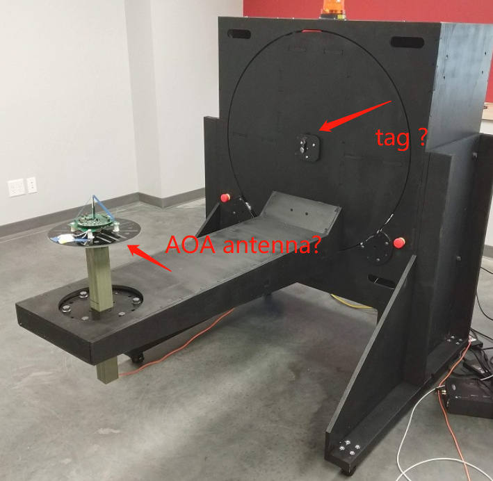
a question as following the picture:
What you label tag is a mounted laser pointer aligned with the elevation axis of the positioner so we can visually get the antenna in the exact center of rotation. The laser pointer is turned on during mounting and turned off otherwise.
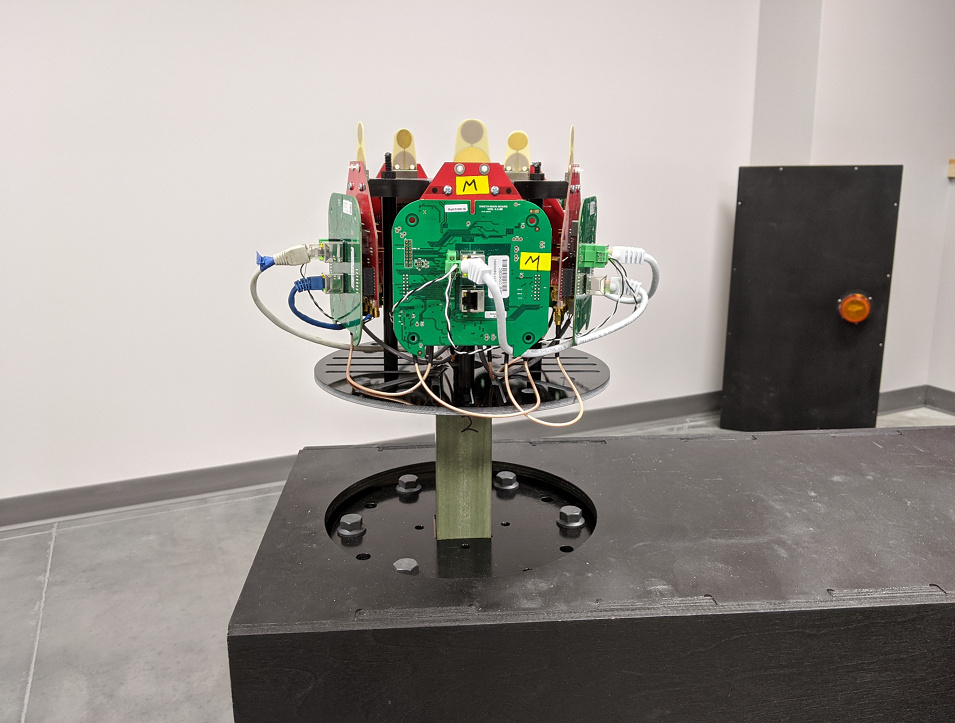
What you label AOA antenna is a single antenna module under test, not one related to AOA. Here is a picture of our early experimental AOA test setup mounted on the positioner:
The AOA system is being reduced to a commercially viable form factor currently. Expected performance is under 1 degree azimuth precision.
Not shown in the picture is the reference antenna, what stands in for the tag in testing. This is a fixed antenna about 3 or 4 meters away that provides the reference for the system. The reference antenna can transmit, receive, or do both depending on the nature of the test. The second photo is roughly from the point of view of the reference antenna.
Mike Ciholas, President, Ciholas, Inc
3700 Bell Road, Newburgh, IN 47630 USA
mikec@ciholas.com
+1 812 962 9408
ok, thanks, when can we buy your aoa device?
another problem, As you can see from the picture, your tag is only rotated horizontally. If the tag is rotated in any direction, will it affect the angle received by the AOA antenna ?
4Q2020.
The system computes azimuth (rotation) and elevation (tilt) plus range to tag, so it is naturally a 3D solution, though the precision varies in the working volume.
In a typical installation, with a unit mounted on the ceiling and antennas pointed down, the azimuth precision is relatively unchanged throughout the working volume. The elevation precision is best when under the unit and then degrades as you increase distance away due to lack of good geometry in that direction. At the end of the range, the elevation precision is relatively poor.
Most users are not that concerned about elevation, they have applications which are satisfied by a 2D solution, so we are building that first. We can make a unit with different antenna geometry which provides a better 3D solution in the working volume but is somewhat larger and more complex. We may do that as a follow on product next year if demand warrants.
Mike Ciholas, President, Ciholas, Inc
3700 Bell Road, Newburgh, IN 47630 USA
mikec@ciholas.com
+1 812 962 9408
For those interested in the antenna positioning in action, here’s a video link:
The antenna is going through a gain pattern test on channel 5 with azimuth covering every degree 0 to 359, and elevation covering every 5 degrees from -45 to +90 degrees. Takes only a few minutes and gives us 0.1 dB resolution. Allows us to compare various antennas designs quickly, and allows us also to test multiple units of the same design to learn unit to unit variation characteristics.
We do a similar thing for phase measurements, TWR distance checks, and other tests. The angular resolution is arbitrary, you can run 0.1 degrees in both axis, though that will take quite some time to complete.
The main requirement is that the antenna electrical center not move distance from the test antenna. This is most clear at the end when the unit resets to home position. This is required to get usable gain data, but it is super critical to phase data measurements where 1.2 millimeters is 10 degree phase shift.
There is no metal in the system from the face of the unit outward, and minimal metal inside the main unit housing (mostly motor and gearbox items).
Mike Ciholas, President, Ciholas, Inc
3700 Bell Road, Newburgh, IN 47630 USA
mikec@ciholas.com
+1 812 962 9408
Our pdoa node flips from 75 to 90 degrees on the right to -60 to -80 degrees on the left, and then returns to the right after 75 degrees on the right. What’s the problem? Thank you very much!