Hello I have one question regarding the simulation.
I’m simulating motor drive, wanted to know how do we separate Power Ground, Analog Ground and Digital Ground??
@Shaurya ,
In a sim, a GND is a GND is a GND. Whether analog, digital or other, a GND point in a sim is a reference of 0V.
In reality, if you have separate GND types on your physical PCB, they are still connected to a single GND reference but may have some low-impedance connections between them. This low-impedance will will have some very low DC series resistance and some low AC series inductance. If you know these values (might be able to measure with a very good LCR meter), you can model these factors in your sim. Sometimes a very good PCB layout tool may provide these values.
Len
Yeah that I Understood.
Lets take one example, I have One digital Signal coming and that is going to gate driver. Gate driver return is connected to Power return like that.
So if i want to isolate it I’'m putting some low resistance between two but it’s not supporting.
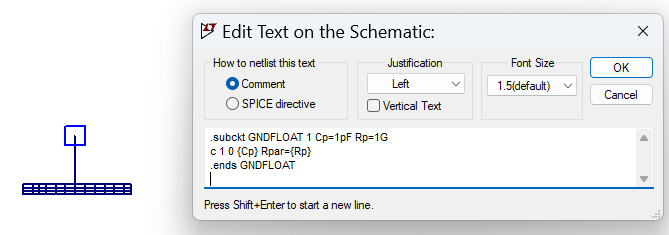
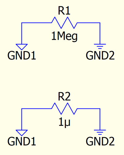
You can do as I did in LTspice:

Ipoma, very low DC series resistance or very high series resistance?
In reality, if you have separate GND types on your physical PCB, they are still connected to a single GND reference but may have some low-impedance connections between them. This low-impedance will will have some very low DC series resistance and some low AC series inductance.
Sure I’ll try this.
Thank you
