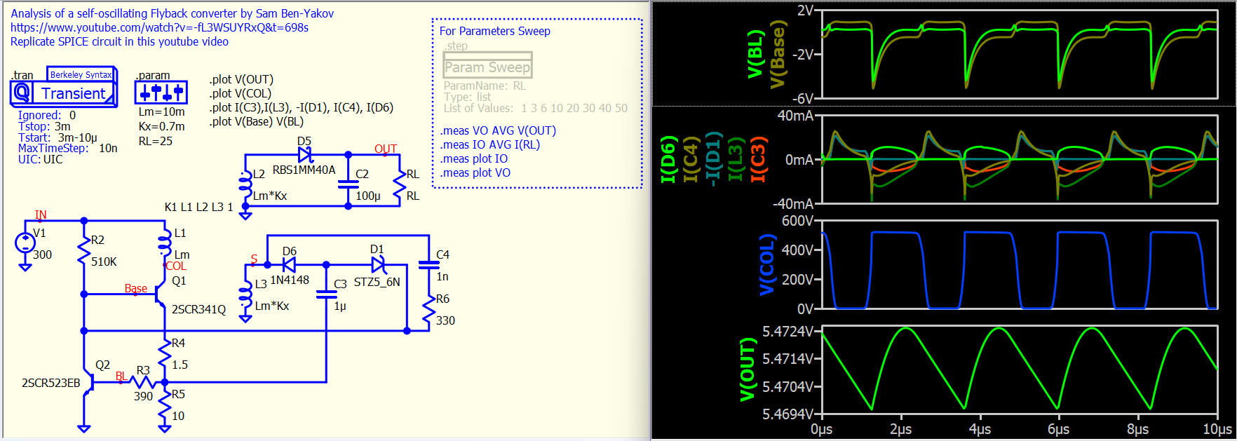
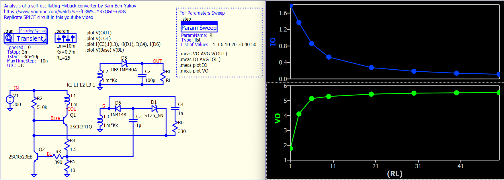
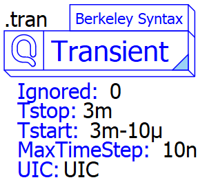
Just came across Prof. Sam Ben-Yaakov explaining a self-oscillating flyback converter (Analysis of a self-oscillating Flyback converter - YouTube). I replicated the simulation circuit shown in his video in Qspice and took this opportunity to demonstrate an experimental feature of the command symbol. In this example, .tran, .step and .param are Qspice symbol. Would like to know how the community feel about drag a command symbol in setup the simulation.
How to actually do that to use these command into symbol?
In my opinion, I will not do this for my own workflow. But, I will do it for creating a training with non Spice savy.
Reason is, I actually like that in Qspice everything is laid bare on the schematic and I dont need to dig into some hidden tab options to see how a certain parameter is set. And after able to memorize many of the command, I find simply typing the whole command is very convenient
However, with long string of attributes I may sometimes forget what those means and I need to check the help or write a new command to see the suggestion.
Meanwhile, for Spice newbie, they may like the fact that all the operations parameter are laid in front of them. But seeing too main foreign syntax may get them confused and overwhelmed.
I particularly like that you can put the definition like this
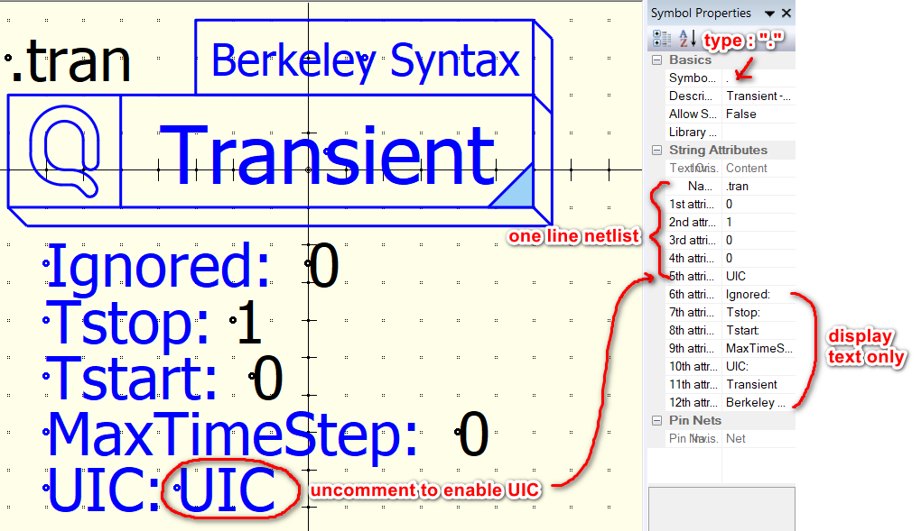
Currently, I have uploaded the command symbol I created on Github. However, it is still in the experimental phase. You can open the .qsym symbol files to see how this type of symbol can be implemented. Basically, the symbol is set up to output a single-line netlist and it begins with “.” Qspice/Symbols-KSKelvin/.command at main · KSKelvin-Github/Qspice
For me, typing commands and using shortcut keys for component placement is definitely the fastest workflow for creating a schematic for simulation, with very minimal drag-and-drop actions. However, some users seem to dislike this approach. For frequent users like us, we are familiar with the command syntax, but many may have difficulty in understanding what that is.
It is clear that Mike will not bring right-click parameter menus to Qspice, but I have found that Qspice symbols have the potential to do more in this aspect. As discussed with Mike last week, he added a new symbol type “.”, making simulation directives supported by a symbol.
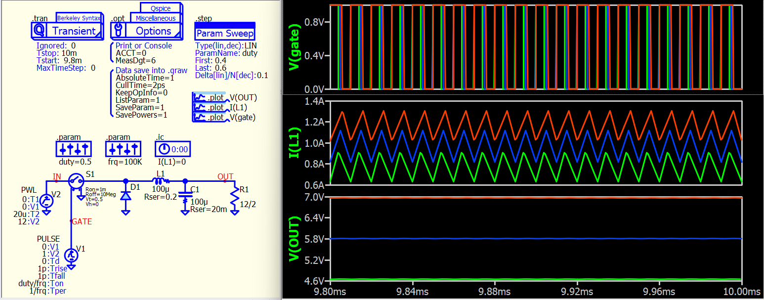
Here is another example, and I have also attached two symbols that I created. Just open them with the symbol viewer, and you will understand how they work. You can go to Github to download more symbols (but I haven’t fully tested them yet).
I would like to gather more feedback from the community to understand if this is something that can be an alternative to their requests.
This feature fits my needs! I occasionally get into a many-day QSPICE session after a few months of inactivity. During the session, I re-discover most of the things I need to remember for good productivity. I believe that this feature will become a great brain-jogging reference for my various “test-bench” circuits I use to understand the details of a circuit I’m developing. Building all the control points as visible elements in the simulation will make a later return to the project much easier.
Shortcut “;” or right click “Do not staff” can disable a symbol. If you want disable .step command symbol in above example, just hover mouse cursor over that symbol (over drawing but not its text), press “;” to disable that.
I would very much appreciate this! While a spice command is easy to memorize and type, it’s hard to read on the page, and the point of using a schematic over a text file is that it’s graphical and easier to read. Maybe an interface that lets one edit the symbol as a spice command or graphically would be useful, so that it can have the graphical benefits of a symbol while keeping the ergonomic benefits of the text based command, if that makes sense