I operate my DWM3001CDK via the battery connector +/- pins, the power is provided by the 3.3V output of a ESP32 device, driven from power supply or 9v battery
I am also trying to power my DWM3001CDK through the +/- battery connector pins. I tested both 3.3V and 5V regulated supplies, but in my case the system does not start and the D20 LED keeps blinking.
Could you please clarify a few points about your setup?
Are you supplying exactly 3.3V directly to the +/- pins?
Are you sharing a common ground between the ESP32 and the DWM3001CDK?
Which firmware is installed on your board (CLI, UCI, or custom firmware)?
In my case, powering externally (3.3V or 5V) does not work, but the board operates normally when connected to a PC via USB. So I am trying to understand what might be different in your configuration.
I am supplying the ESP32 regulated 3.3v out, I have not measured it. my other 3.3v devices work as well.
yes, sharing ground
I am currently using the QANI firmware, Apple only
there was a topic on the Fira firmware a year or more ago about USB power
and I thought there was a line of code change to not require USB on the UCI/CLI firmware
I am currently doing dev on the UCI firmware, but won’t be using the 3001CDK board there
(Nordic 52833 too small memory for our needs) and using USB for debug too, so I have not encountered this problem
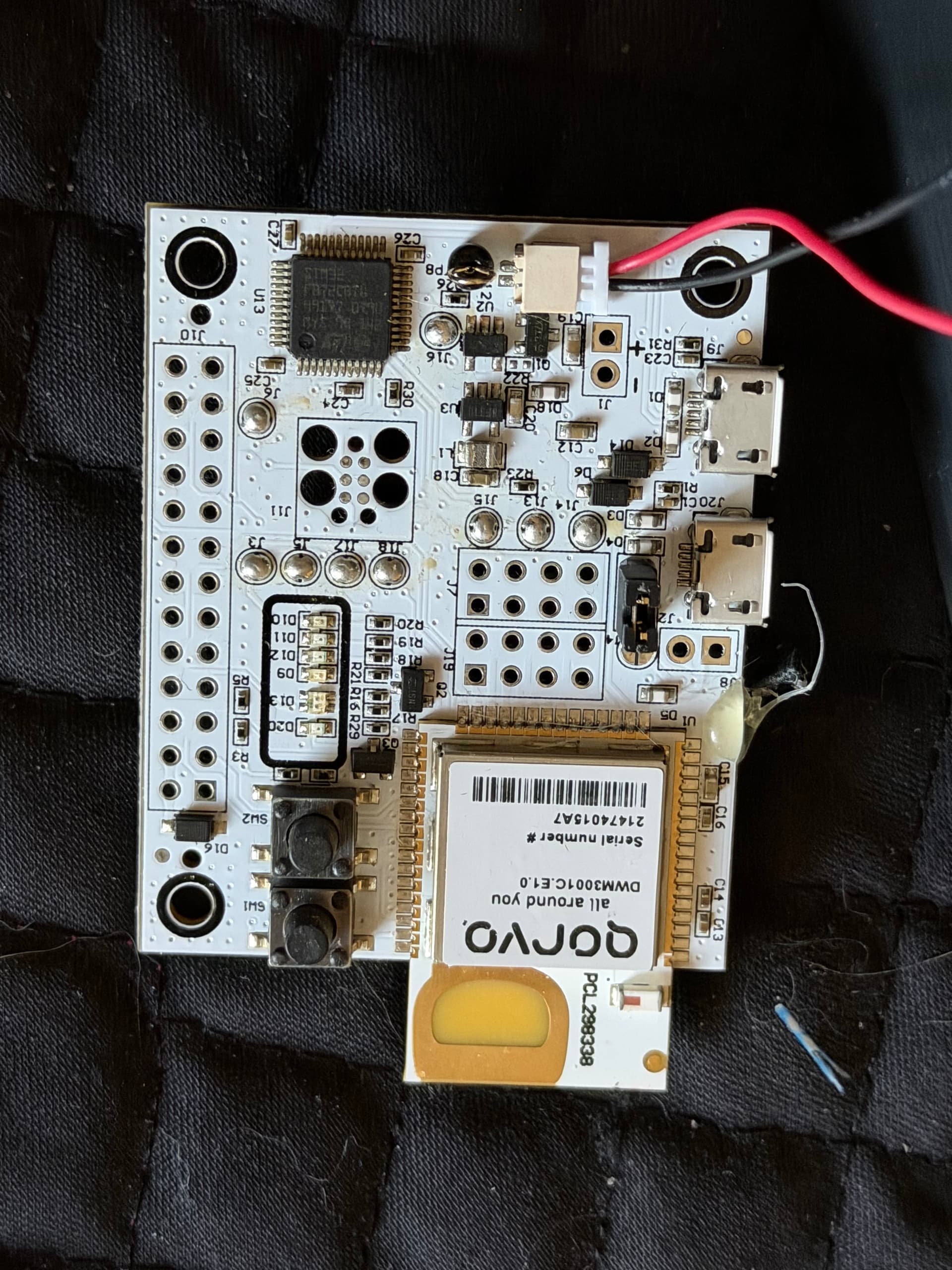
you do note that the +/- are backwards from the normal color on pre-built connectors..
+ would be black, and - is red.. at least for the wire assemblies I purchased they are backwards,
I will test the board with QANI firmware as well. Regarding the battery connector polarity, I am confident that I connected the + and – pins correctly. I double-checked the wiring and polarity carefully.
At this point, I suspect that in UCI and CLI firmware there may be a condition where the firmware expects USB presence (or USB enumeration) during boot. That could explain why the board works only when connected to a PC and not with standalone external power.
I will test with QANI firmware and report back with the results.
Yes, I agree with you. At this point I also believe the issue is not related to the power source itself.
The behavior strongly suggests that the module firmware is waiting for a USB connection (or USB enumeration) during boot. When connected to a PC, everything works normally, but when powered externally, the board does not complete initialization and the D20 LED keeps blinking.
I have already tried some of the suggested solutions mentioned in this forum, but in my case none of them solved the issue.
So the problem seems to be firmware-related rather than power-related.
What would be the correct way to allow the board to operate fully standalone without requiring a USB connection during boot?
The problem with the power bank is likely related to the fact, that the nowadays power bank are designed for the phone charging, where the current is expected to be significantly higher than what the DWM3001CDK would consume with common QNI or RTLS firmware.
For this reason the power bank would likely cut off the output to the DWM3001CDK.
If you need to power the DWM3001CDK from the battery then I would recommend using a LiPo and power it through the battery connector available on the DWM3001CDK board.
Thank you for your response. I was aware that the power bank shuts off its output when the current draw is too low. I have resolved the issue; the system is now operating smoothly without requiring any changes to the code or hardware configuration.
It would be very helpful to have a reference page explaining the LED status indicators on the board. If such documentation exists, I was unable to locate it. Based on my observations:
When I power the system via the J20 port or the external +/− pins, the D20 LED blinking red indicates that the system is running. In this case, the module operates normally.
When I connect the board to a computer via USB, the green LED on D9 turns on, which likely indicates that a data connection with the PC has been established through the D+/D− lines.
When I send commands to the module via the CLI using Tera Term (e.g., resp, initf, etc.), meaning when communication with the module begins, the blue LED on D10 turns on.
In conclusion, there is no issue on either the software or hardware side that prevents the system from operating via USB or external power. The module functions properly with both power supply methods. By analyzing the issue in this way, I was able to reach a solution.