Hi Everyone,
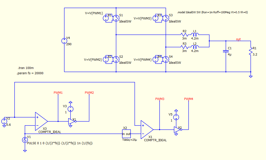
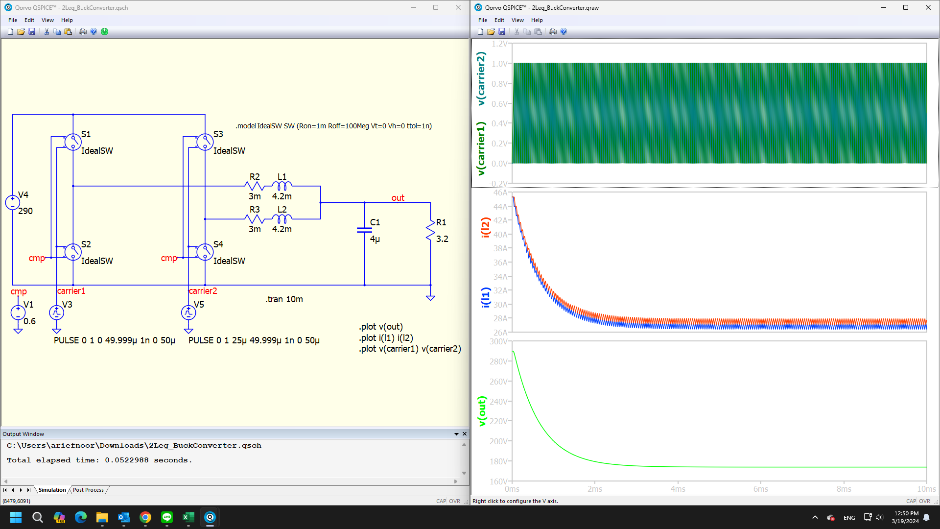
I have simulated this circuit in PSIM and it works. But when I tried it in QSpice, the voltage didn’t come out. Is there something wrong with the circuit or the PWM signal? I’m still not familiar with this software
Are you sure that your principle control of the converter is right?
~mac
It seems correct, because this is actually a normal open loop buck converter control. I have applied it to PSIM and it works. If something is wrong, please correct it.
~asep
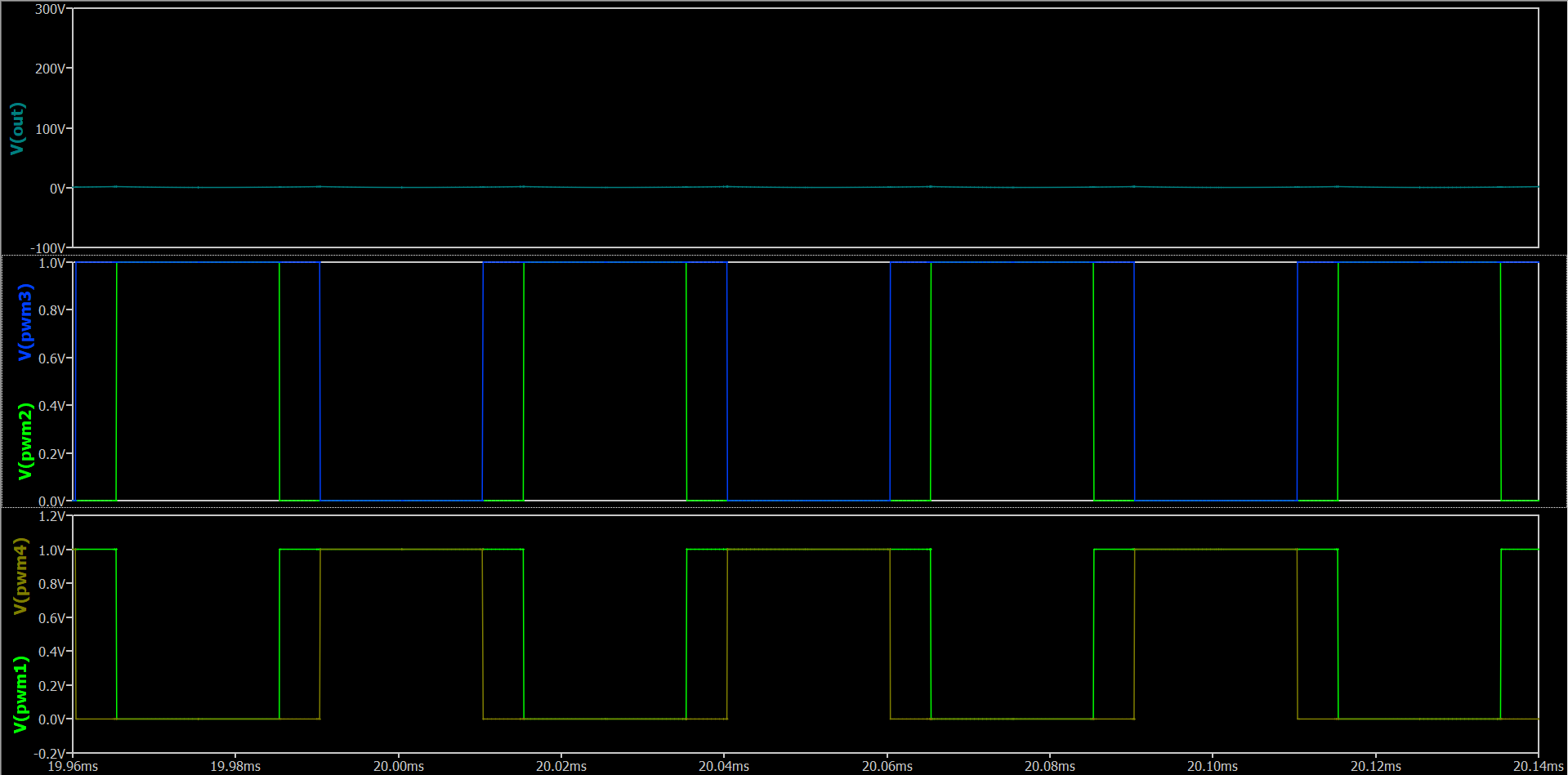
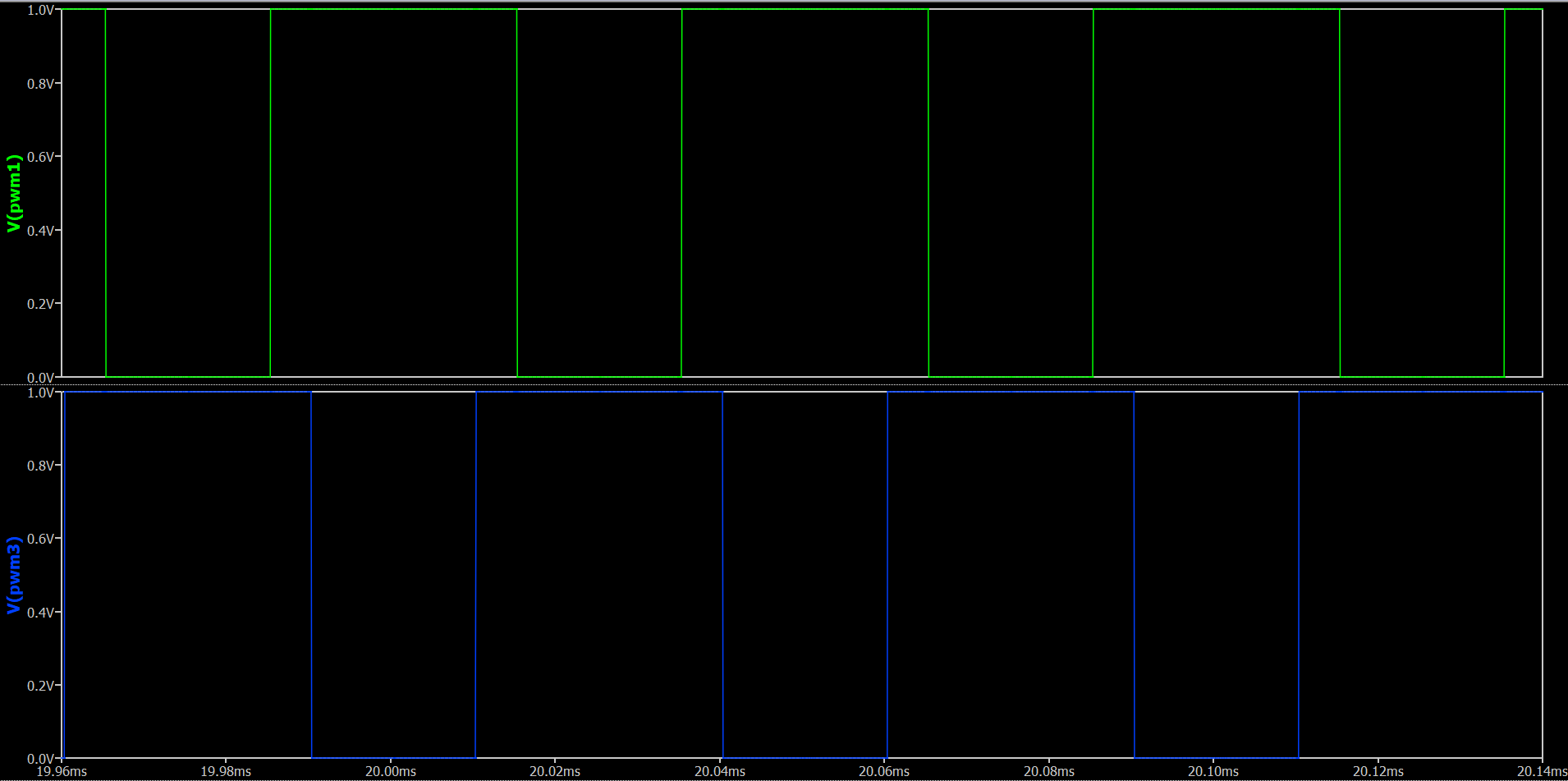
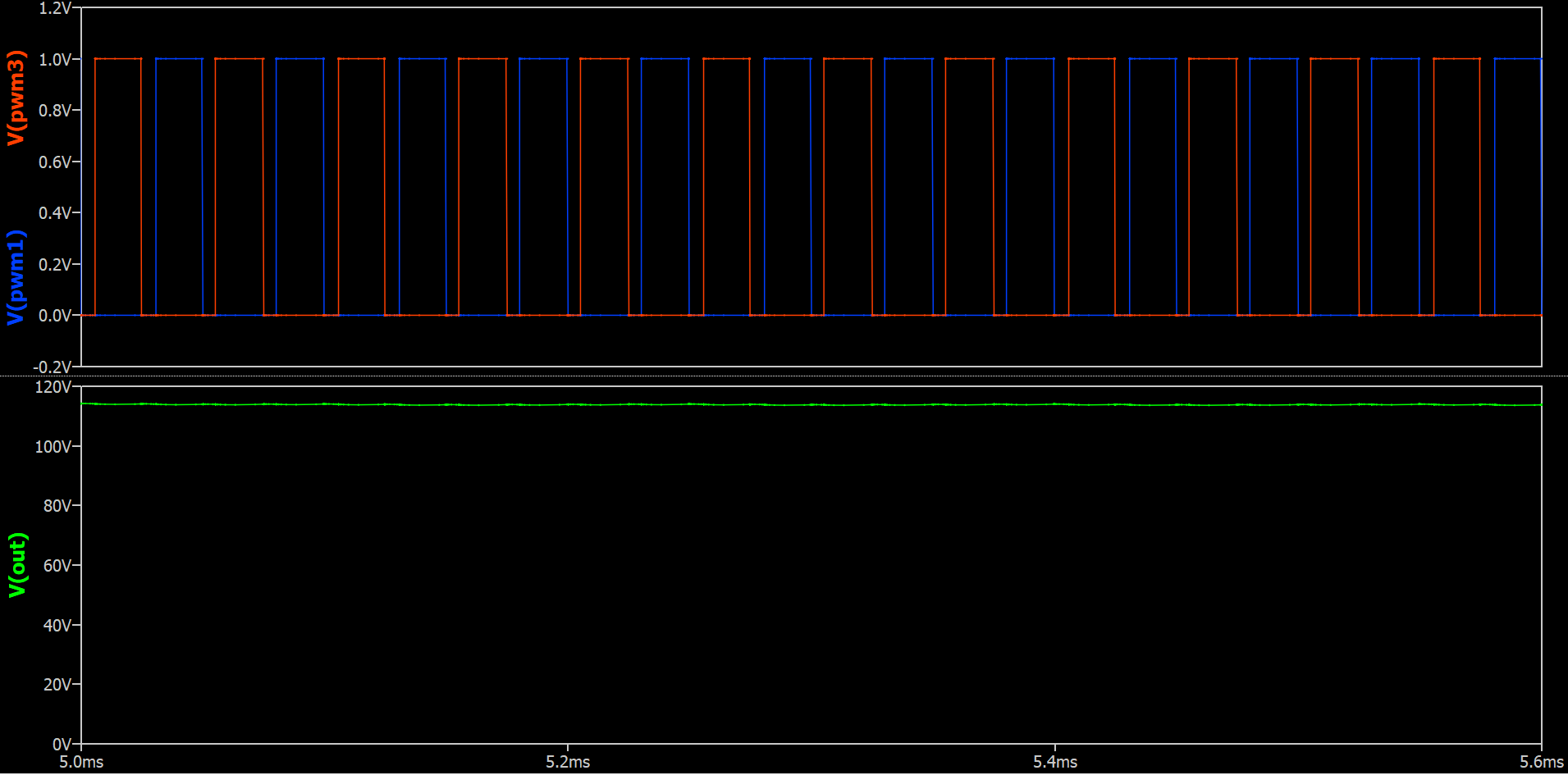
In my understand of two leg buck converter phase shift each leg is 90 degres. Are your phase shift pwm1 and pwm3 is 90 degres? I think it’s not.
Send your simulation file here, I’ll try.
I can’t upload it, there is a warning that new users cannot upload files. I uploaded it to this drive
ok. please waitting.
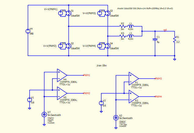
I have tried it and it works, thank you sir.
Yes, i’m from indonesia. Thank you for the advice
Why does the output voltage start at the 290V input voltage? I think this is an error within Qspice. This same issue has happened to me as well when simulating a buck converter. My fix was to apply the duty cycle command as a step after the simulation has begun.
There are two ways to set up the correct initial conditions for the circuit above:
- Add
DC=1for voltage sources V3 and V5, to force S1, S3 to OFF in DC analysis. - Add
.ic V(out)=0 I(L1)=0 I(L2)=0to force initial conditions.
Alternatively, some may include UIC in .tran (although this is not recommended).
SPICE calculates the DC solution before the transient simulation if .tran is used. This behavior is not a bug but rather how SPICE process.
3 Likes
Thanks, I will give that a try.