I have a circuit with this Infineon part, it works perfectly with just one part on the schematic (X1). When i added a second part to the schematic (X1 & X2) I get the bellow readout in the output window:
The table function works best with constant values in the table:
** “G_L_DT VCC_1V LOFF VALUE={TABLE( V(VCC_1V,LOFF) , 0,0 , 10M, I_DT( V(DT,HV_RTN)))}”**
The table function works best with constant values in the table:
** “G_L_DT VCC_1V LOFF VALUE={TABLE( V(VCC_1V,LOFF) , 0,0 , 10M, I_DT( V(DT,HV_RTN)))}”**
This reminder is returned regardless of how many 1ED44176N01F in schematic. Possibly this won’t affect simulation result.
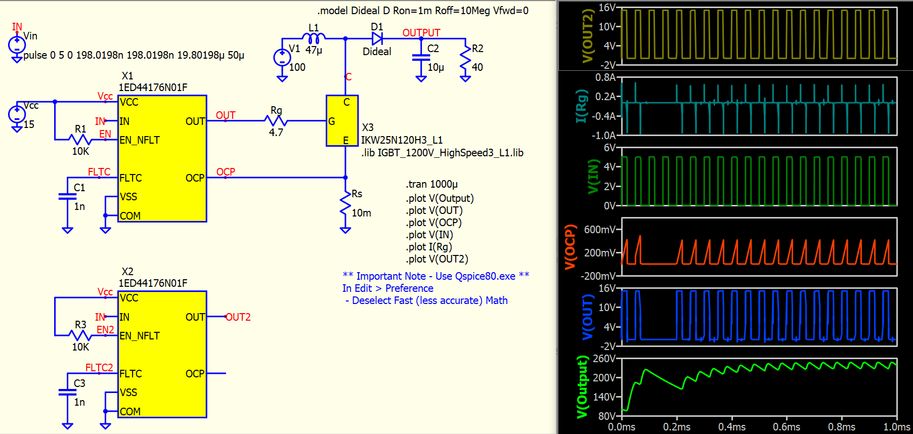
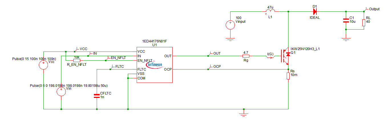
Here is a circuit which replicate results of demo testbench in 1ED44176N01F Infineon model, and to include a dummy X2 1ED44176N01F.
Parent.Infineon.qsch (34.0 KB)
IGBT_1200V_HighSpeed3_L1.txt (36.4 KB)
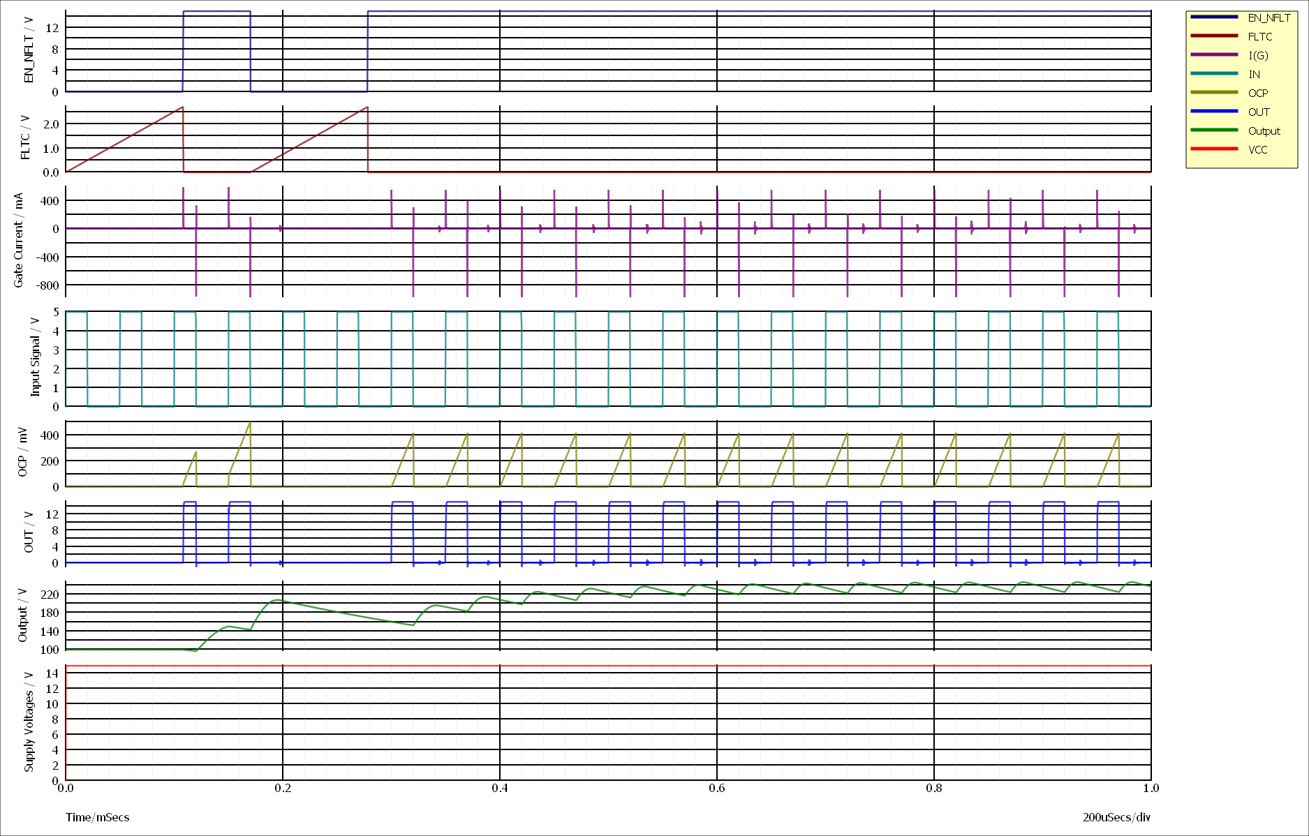
Compare “FLTC” and FLTC2".
In my schematic, its seems like the parts sub-circuits are somehow linked. I can see that the signals on X1 are affecting what X2 is doing.
Also, if I separate the returns between the two parts, the simulation crashes.
Edit:
I have found that the return for both devices needs to be at “0V”, not some other node in the schematic. I think there is an internal sub-circuit which is referenced to “0V” within the model.
1 Like