I see your point now. This is one of the reason why at the beginning I am unsure if a transmission model can be simulated with no ground node at its 2nd and 4th node.
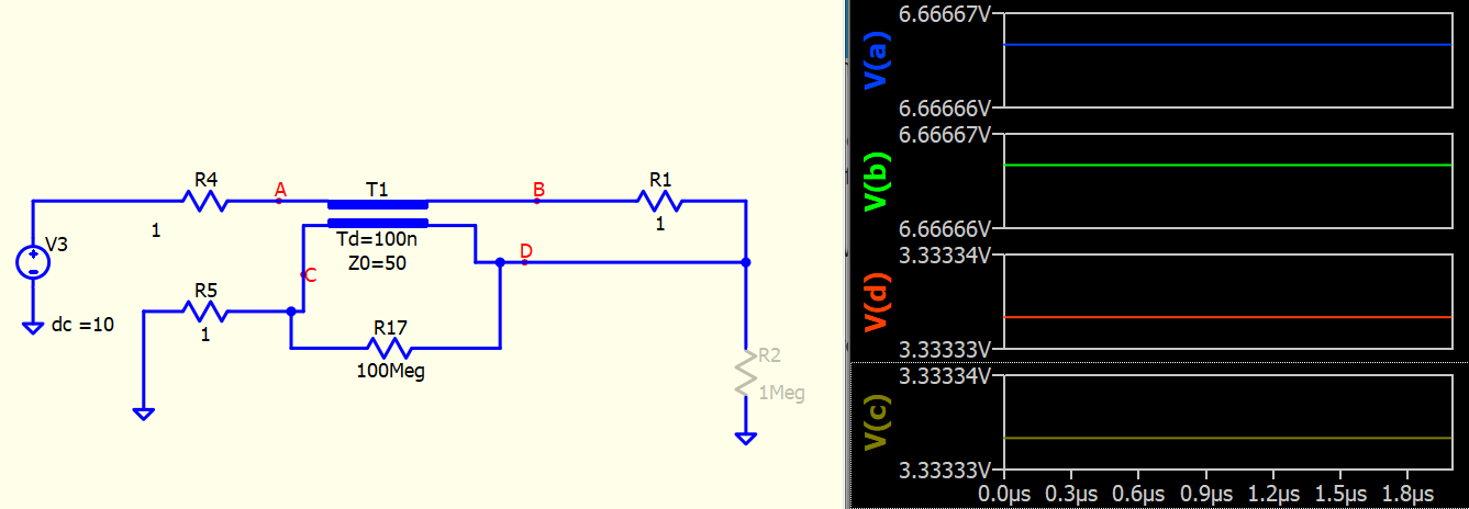
What you can see is that, the simulation is forcing V(D) to ~0V to give correct differentiate voltage but not absolute voltage. Currently, if you disable R2 and add a resistor connecting V(C) and V(D), you will get V(A)=V(B).
But if you have anything in right side having a ground path, V(D) will goes to 0V again.
OR, short V(C) and V(D) and you will have right side voltage not be affected by R2.
Possibly this topic need expert in transmission line simulation (line is floating) to answer.