For this week’s QSPICE Schematic Capture, we have an impressive system-level simulation by our friend Mohamed Aly, who earned his Master of Engineering in Electrical Engineering and Embedded Systems from Ravensburg-Weingarten University of Applied Sciences in Germany.
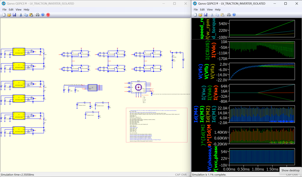
The schematic models a complete low-voltage, three-phase traction-inverter system. It brings together:
• A three-phase inverter power stage
• Six isolated gate-driver models
• A field-oriented control algorithm
• Current and voltage sensing
• A motor model with speed and torque feedback
• Closed-loop startup and acceleration
The plotted results show the commanded speed ramp, motor speed and torque, DC-link behavior, control voltages, three-phase currents, individual switch currents and PWM switching activity.
Why does this matter?
A traction inverter is much more than six power switches. Its behavior depends on the interaction among the control algorithm, gate drivers, power stage, motor and mechanical load. Simulating these elements together allows engineers to study startup, acceleration, current regulation, switching behavior and system-level stability before committing to hardware.
This is also an excellent demonstration of QSPICE’s mixed-signal capabilities. The field-oriented control code, isolated gate-driver models, switching power stage and motor can all operate within the same simulation—connecting embedded control directly to the power electronics it governs.
Thank you to Mohamed Aly for sharing this ambitious and highly detailed project with the QSPICE community.
QSPICE: From control code to switching waveforms to mechanical motion—all in one simulation.
Please send any schematic submissions to tim.mccune@qorvo.com.
Schematic Capture Post #101
foc3ph.cpp (11.8 KB)
UCC5350SBD.qsym (777 Bytes)
LV_TRACTION_INVERTER_ISOLATED (2).qsch (96.1 KB)
foc3ph.cpp (11.8 KB)
UCC5350SBD.qsym (777 Bytes)
UCC5350SBD_QSPICE.lib (8.0 KB)