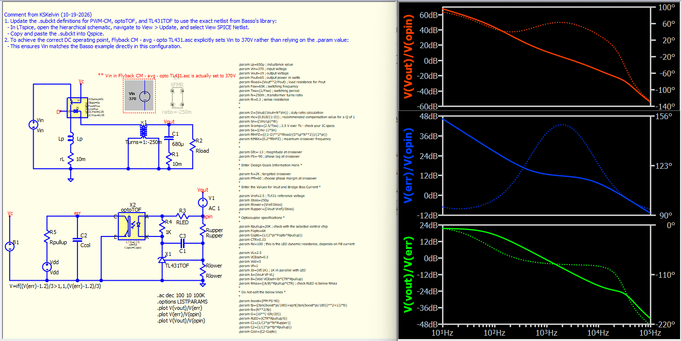
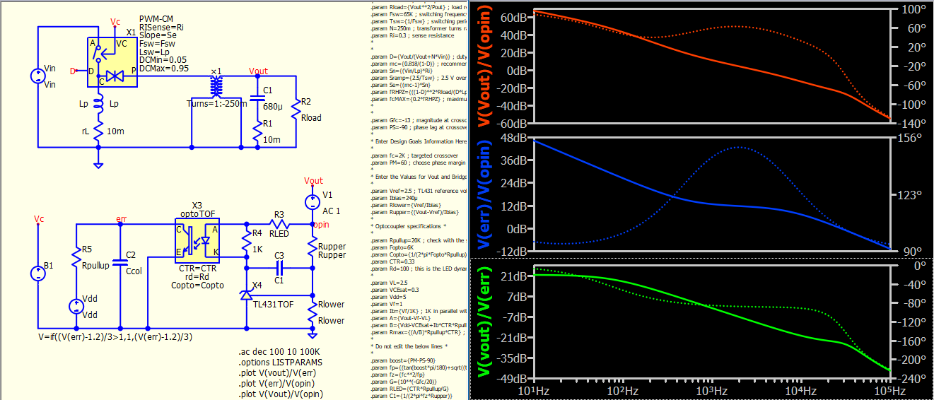
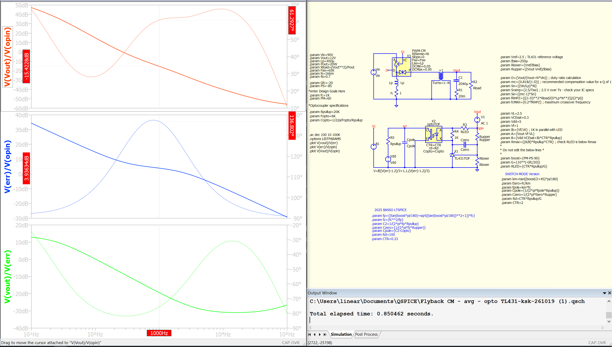
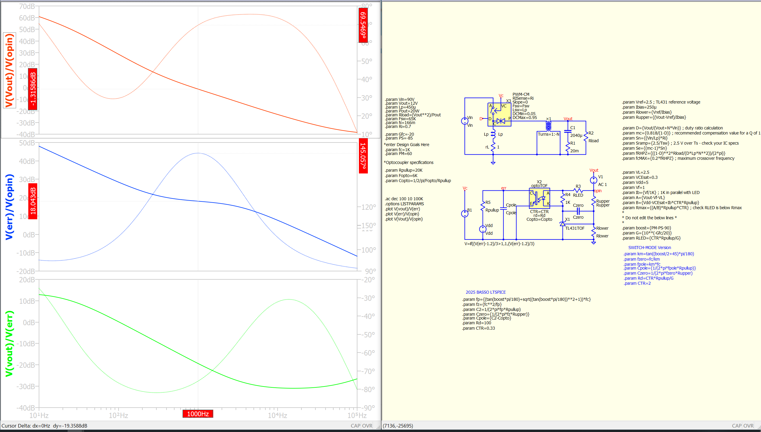
Hello everyone, I’m new to QSPICE. I’m currently porting a small-signal analysis project for a flyback converter from LTSPICE to QSPICE, but I’ve run into a confusing issue.
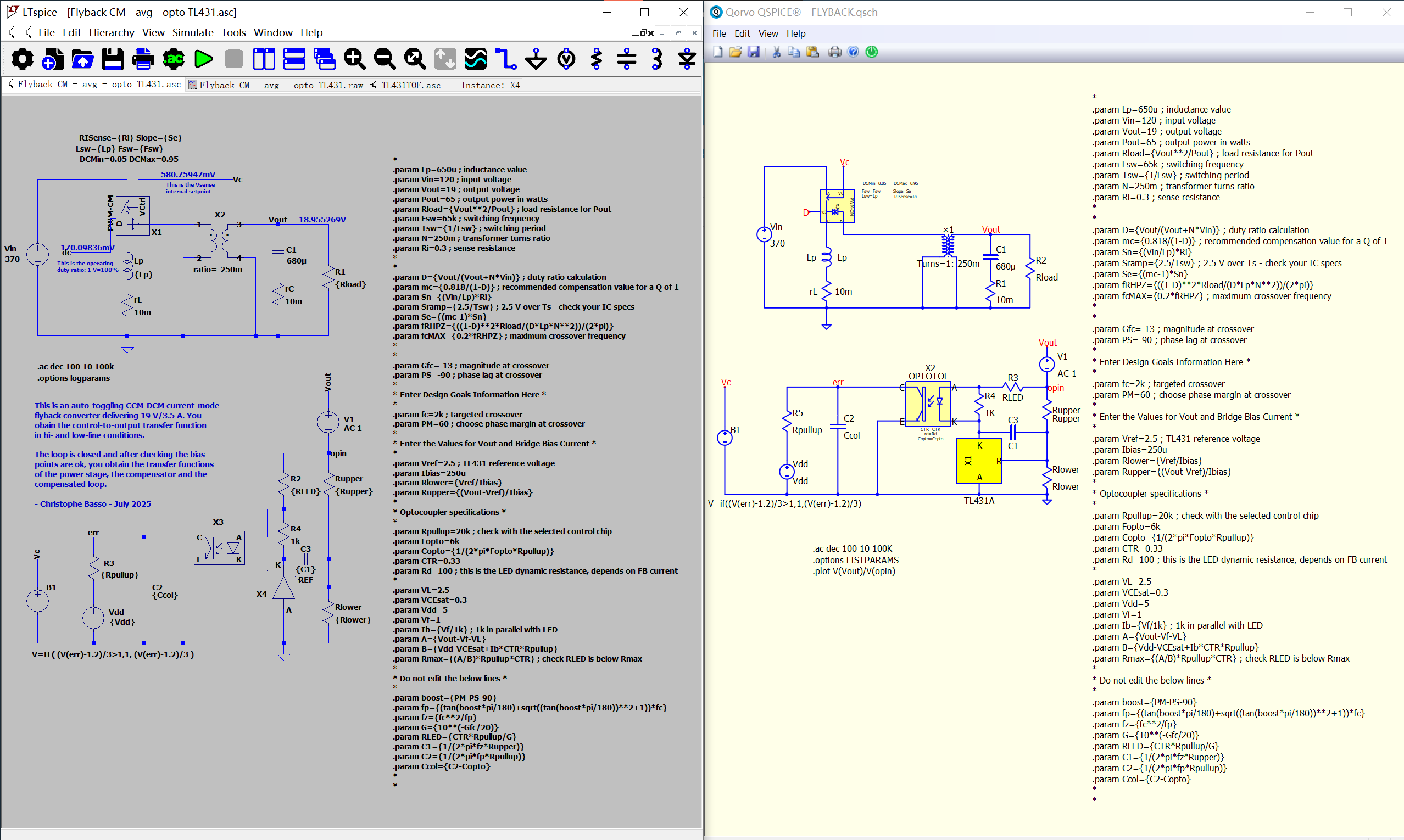
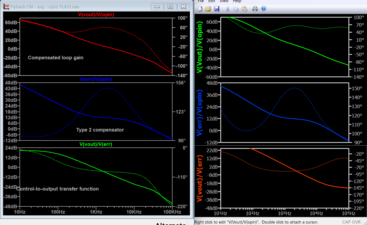
The LTSPICE schematic is from a free public simulation shared by Mr. Basso on his personal website. I have recreated every component in QSPICE one by one: the PWM-CM block, the optocoupler model, and the TL431 (I generated the TL431 part directly by pasting the netlist code into QSPICE). However, the resulting output waveforms are incorrect
LTSPICE gives DC = 170 mV, while QSPICE only shows 10 mV.
For VC, LTSPICE yields 580 mV, but QSPICE gives merely 211 mV.
Honestly, I have no idea where the error originates and I’m completely stuck.
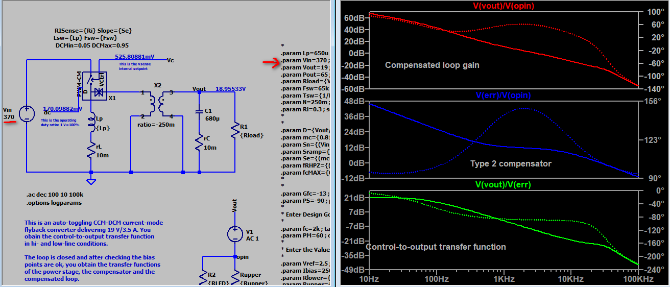
I cannot upload the original LTSPICE files. The simulation is available from Mr. Basso’s page: https://powersimtof.com/book11.html
The file name is Flyback CM - avg - opto TL431
This seems a bit cumbersome. I would greatly appreciate any hints pointing to potential root causes.FLYBACK.qsch (20.9 KB)
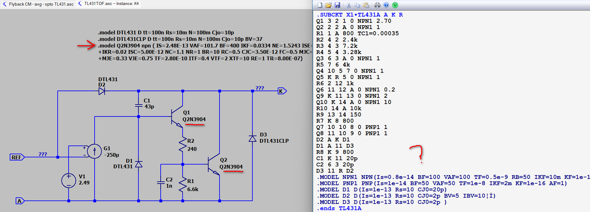
It appears you didn’t fully rebuild the circuit according to Basso’s example. For instance, the netlist in your TL431A model doesn’t follow the hierarchical schematic TL431TOP.asc used in Flyback CM - avg - opto TL431.asc
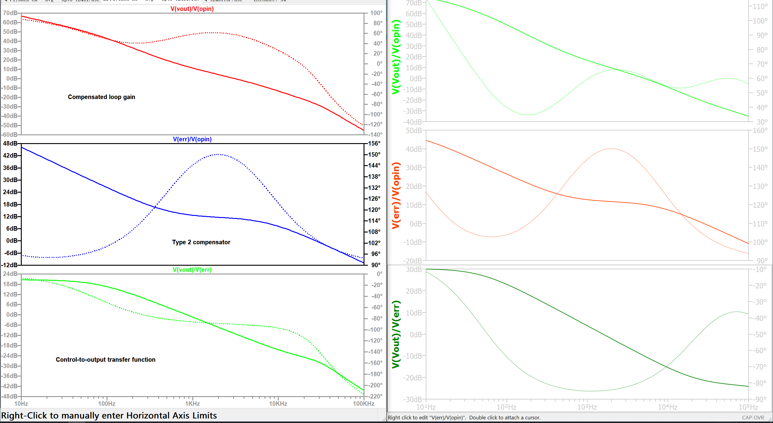
When matching y-axis of your Qspice results to match LTspice, the discrepancy isn’t actually that large. Therefore, the deviation is likely due to differences in how the Qspice circuit was constructed.
I found my mistake. Inside the PWM-CM block, there is code measuring the current between nodes a and b. I had the 0V voltage source placed backwards.
(Did I misremember? I recall that for current measurement using a 0V voltage source, QSPICE uses the opposite polarity compared to LTspice. I was confused about this at the time)
The current direction of a voltage source is identical across all SPICE platforms. The only difference in Qspice is that when you probe the current of a voltage source (e.g., V1) from the schematic, the waveform viewer automatically returns -I(V1) for a non-zero voltage source and I(V1) for a zero-voltage source.
Normally, we want to probe the current flowing out of an active voltage source, which is why -I(V1) is the most logical default. Conversely, a zero-voltage source is typically used as a current monitor, where we want to see I(V1). For this reason, Qspice automatically determines whether to apply a negative sign to the probed waveform based on the source type. Qspice doesn’t change representation of current direction, all SPICEs follow the same rule.
@abornblatt please let me know if you can get same results as the book, I kinda did the same excercise back in 2023 when Qspice was new, and I couldn’t get the same results. My conclusion, not knowing if it was right in all conditions, was that the behavioral sources isn’t behaving the same in all spice programs. I also noted that some Model tl431 developed in ltspice IV didn’t work the same in the current ltspice at that time either.
The .dc results also well match, V(Vout) in Qspice is 18.9553V and LTspice is 18.95533V, V(Vc) in Qspice is 525.777mV and LTspice is 525.80881mV
[*note : @abornblatt I just noticed that in the Basso example, the voltage source Vin is set to 370V, whereas .param Vin=120. If I update .param Vin to 370V as well, V(Vc) matches correctly. Therefore, the computational difference caused by the BJT .model in the TL431 is almost negligible. I hadn’t realized the discrepancy stemmed from the .param computation due to the mismatch between the V-source voltage and .param Vin in the Basso example.]
@Akillion In conclusion, I think we can match the results between LTspice and Qspice in this example, without requiring any tweaks to the models or subcircuits. Initially, @abornblatt tweaked the LTspice subcircuit into Qspice, which resulted in a mismatch. Above discussion consisted of copying the exact .subckt from LTspice for use in Qspice, the method markup in my schematic.
@KSKelvin Great explanation on migrating the project.
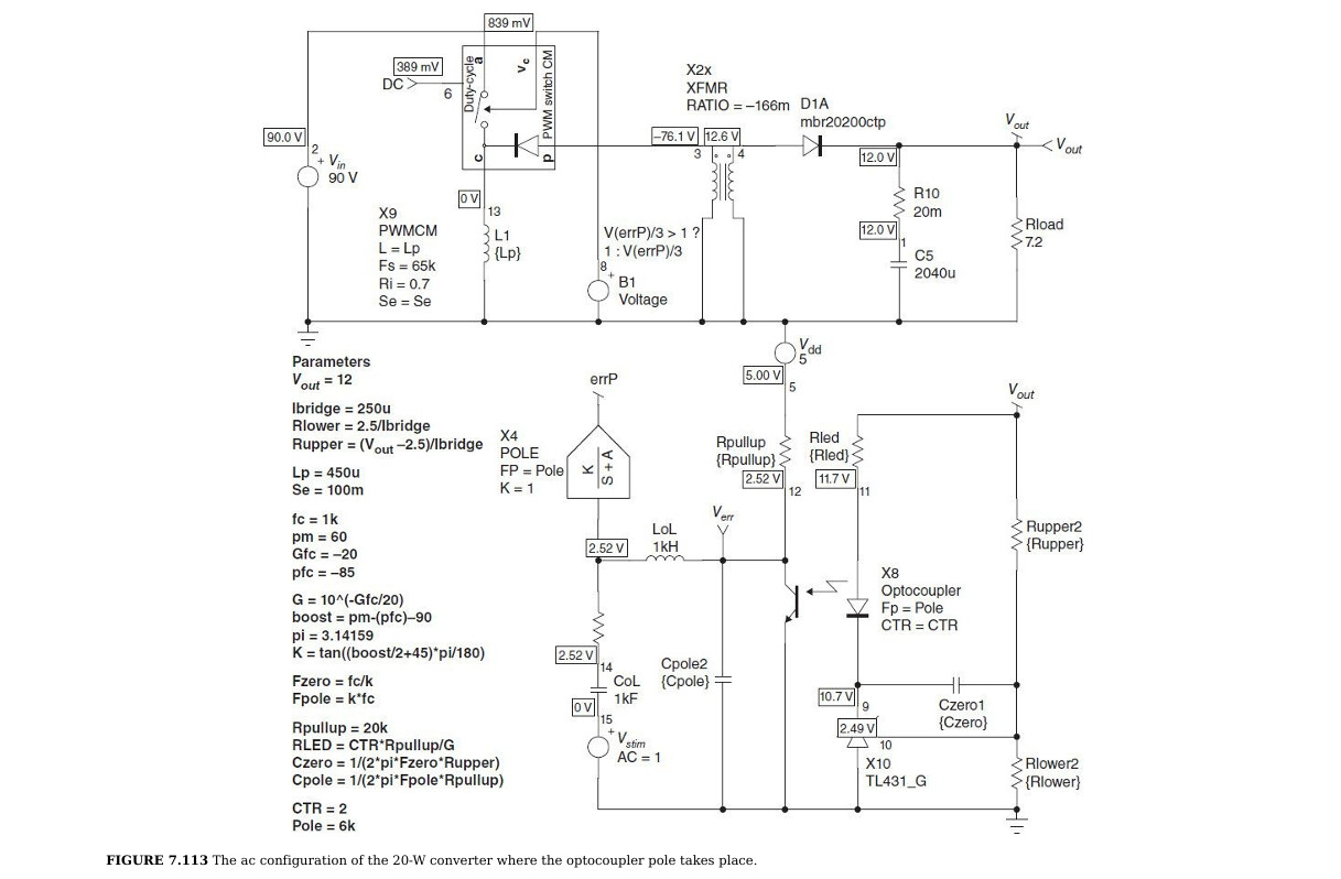
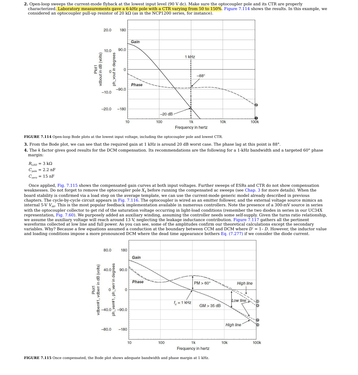
By the way,the LTSPICE project was published publicly by Basso around 2025. So I suspect what you are referring to is the small-signal analysis simulation on page 544 of Switch-Mode Power Supplies, Second Edition SPICE Simulations and Practical Designs (Christophe Basso).
The 2025 LTSPICE project computes zeros and poles differently from the approach adopted in the book Switch-Mode Power Supplies.
I’m not sure how the optocoupler is modeled in Switch-Mode Power Supplies. If we ignore optocoupler differences — I suspect the simulation mismatch comes from different optocoupler implementations — the results are clearly inconsistent.
I don’t quite get that.
Initially, we reviewed an example Flyback CM - avg - opto TL431.asc , which included in the ZIP file download from Basso’s website (https://powersimtof.com/book11.html), and the simulation file I modified from your work, named Flyback CM - avg - opto TL431-ksk-261019.qsch is created. If we align the Vin and .param Vin, their result both aligned.
So, the mismatch you are referring to, is from a new reference or something else?
Or, you are expecting to just modify Flyback CM - avg - opto TL431-ksk-261019.qsch can give you the result from this book schematic?
But this book schematic with many elements nothing look like the example we discussed. Did you modify the LTspice example Flyback CM - avg - opto TL431.asc and can get the book result?
I guess if you don’t have all the exact model and subckt from this page, it is not possibly to replicate this page result. Basso’s work consist many input parameters and complex subcircuits and formula.
please let me know if you can get same results as the book, I kinda did the same excercise back in 2023 when Qspice was new, and I couldn’t get the same results.
However, the book at https://powersimtof.com/book11.html was published in 2026 and finished in 2025. Therefore, I suspect the simulation he tried to replicate comes from another book by BassoSWITCH-MODE-SUPPLIES which was released before 2023, around 2014 if I recall correctly.(Perhaps my guess is incorrect?Akillon didn’t mean that?)
Due to differences between these two schematics, my hasty modifications failed to achieve successful replication.
The migration of this simulation project from LTspice to QSPICE has met my original goal. I am now learning optocoupler and TL431 compensation, as I still have limited understanding of this part.